Projects
These are some of my personal projects.
Click on them to see more information.

The Gaggiuino mod
While this isn't my own modification, its quite involved. The Gaggiuino mod takes a Gaggia Classic Pro and adds many features that allow for better espresso. The Gaggia Classic Pro is a very basic machine. It doesn't allow you to control the brew temperature nor the pressure. These are the two main factors to making better espresso. The Gaggiuino mod details parts required, has thorough wiring diagrams and has software written to give easy user control over temperature and pressure profiles for brewing.
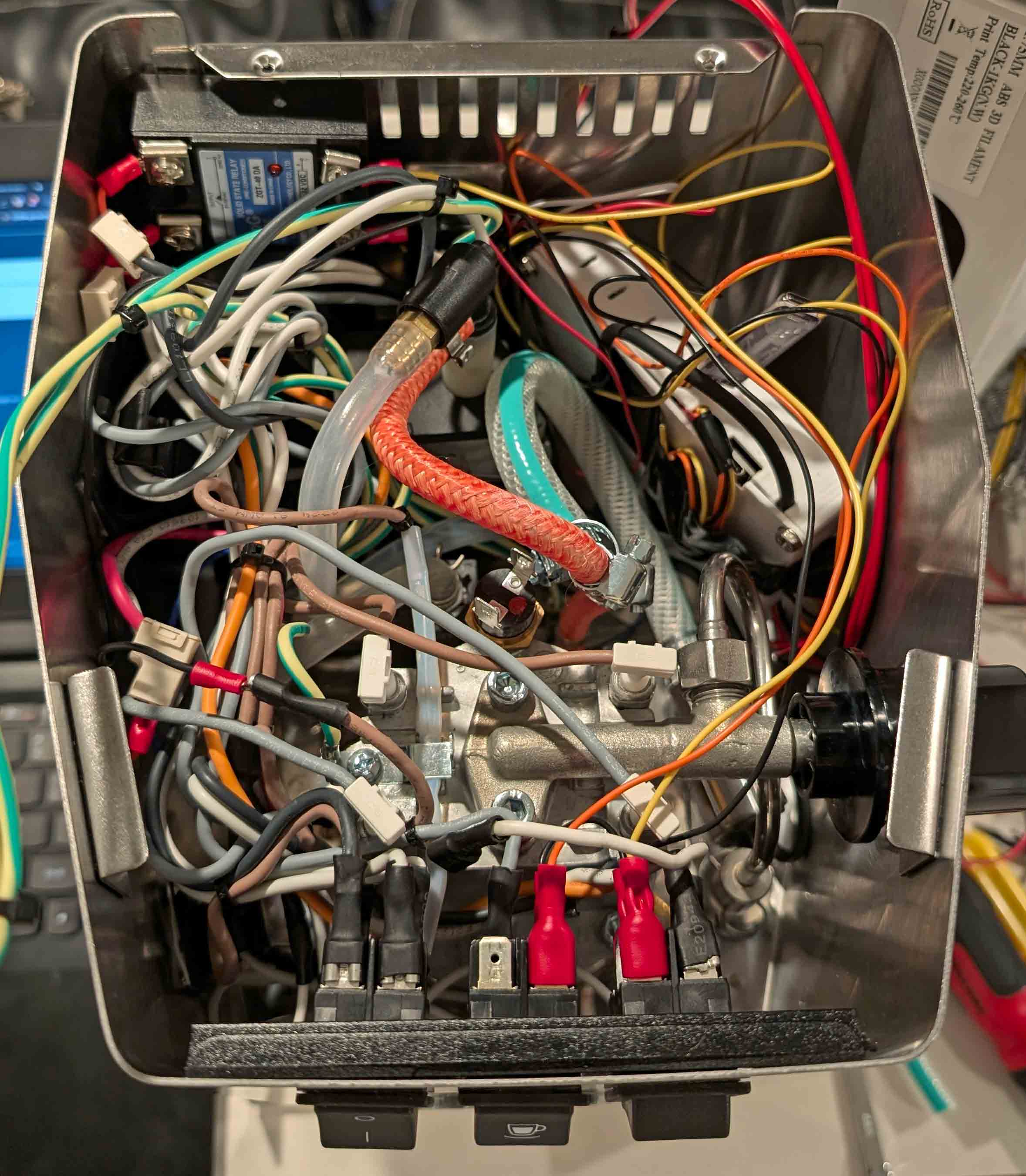
This modification starts off with a 3D printed enclosure to hold the basic parts. It holds a few analog to digital converters to read the temperature probe and pressure probe, an AC dimmer to control how quickly the pump runs, a relay to control the pressure valve, a STM32 microcontroller, and a few components to step 120VAC down to 5VDC.
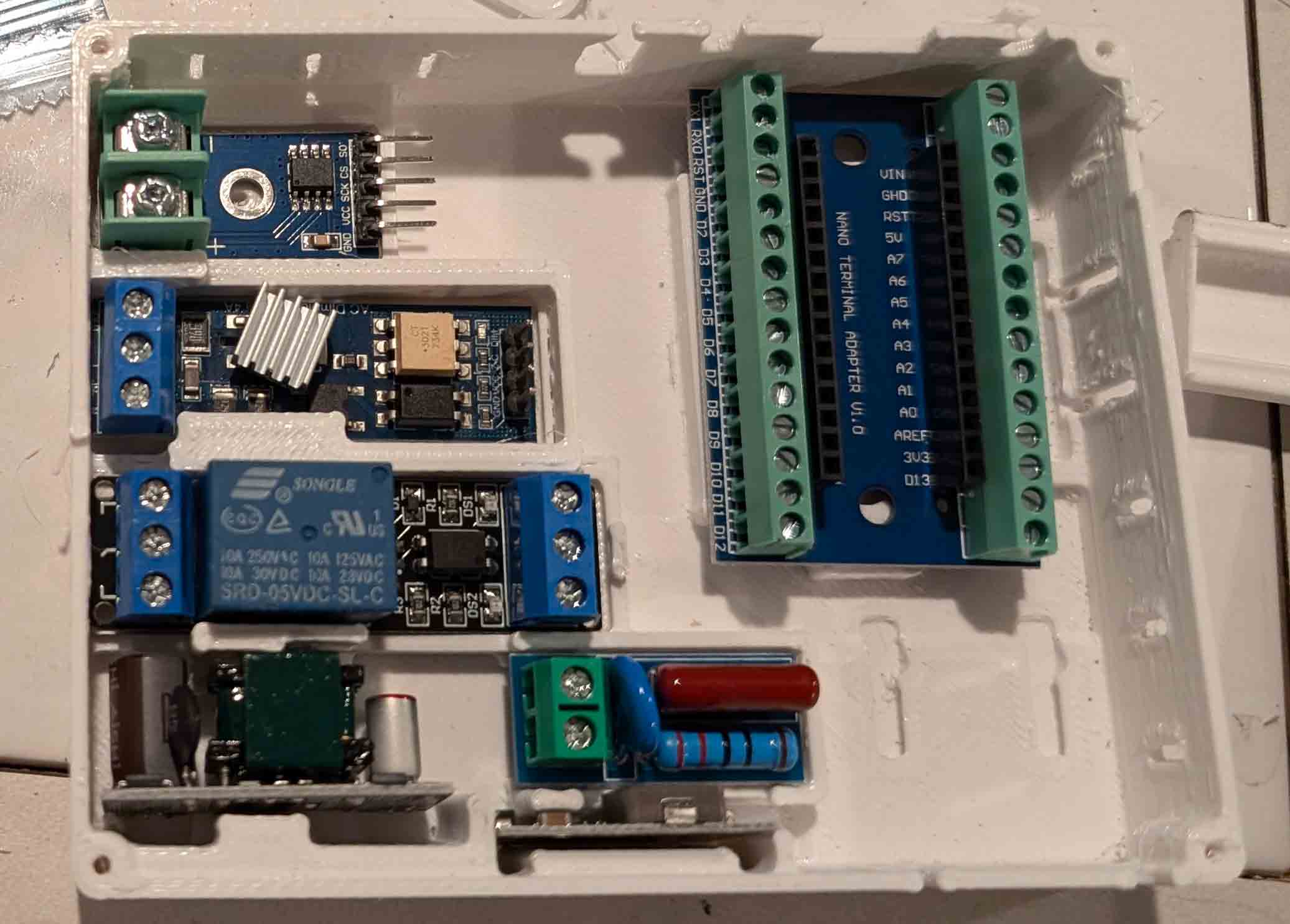
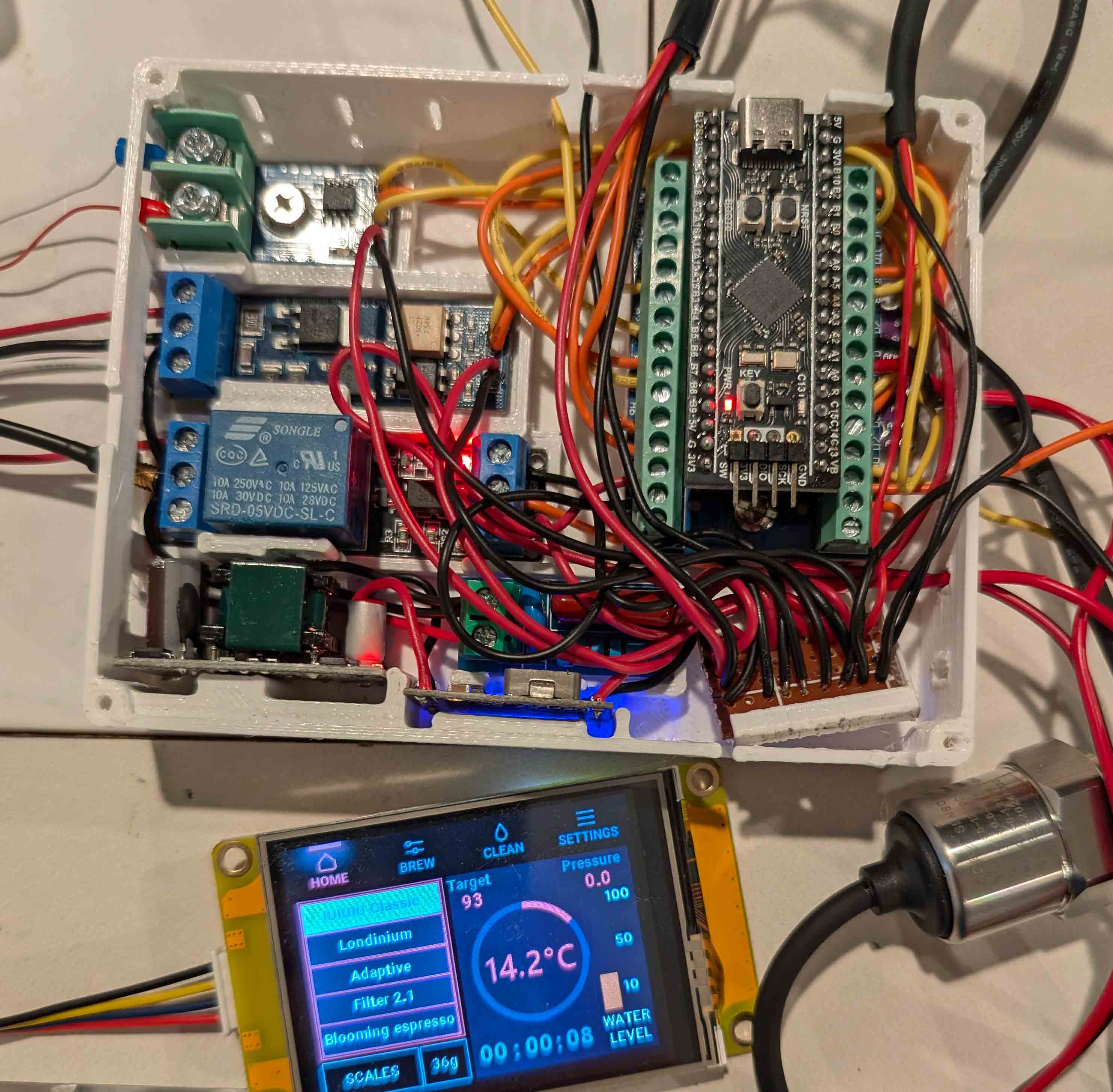
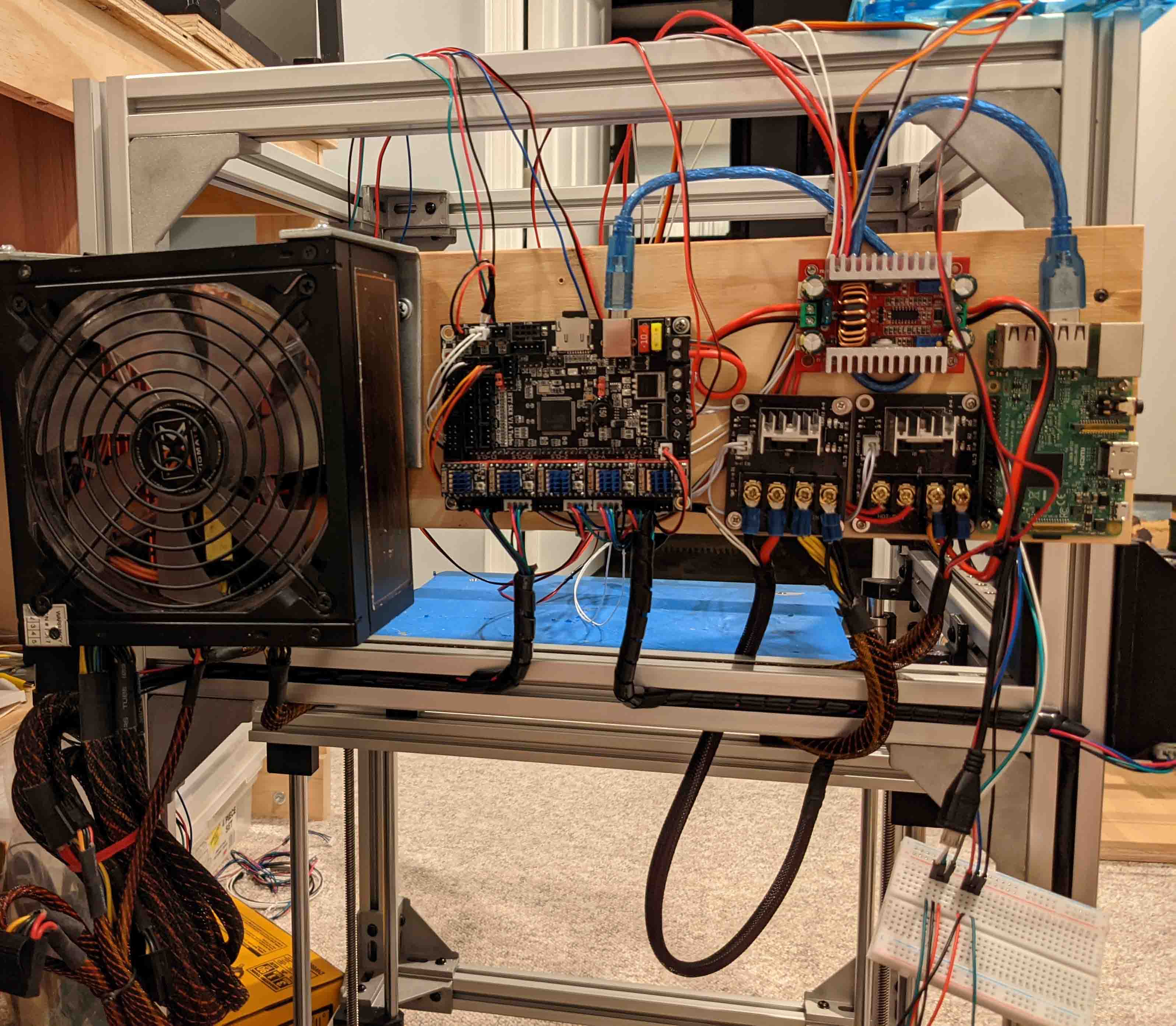
Following the detailed wiring diagram, the enclosure quickly becomes pretty busy. Thankfully flashing the microcontroller and testing the system worked without an issue.
The next step was a bit frightening since I had to hack up my nearly brand new machine and definitely void its warranty. After splicing into the factory wiring harness, the 3D printed enclosure with the added components tucks into the back of the machine.
After cramming everything inside of the casing and reassembling the machine, I was able to test out the functionality. I learned that its possible to wire a thermal probe backwards. I never knew that a thermistor could be polar. After fixing that issue and not having a negative temperature, I was able to brew espresso!

I probably won't have a job at your local Starbucks any time soon, but it's fun to try making different drinks!

HevORT-C
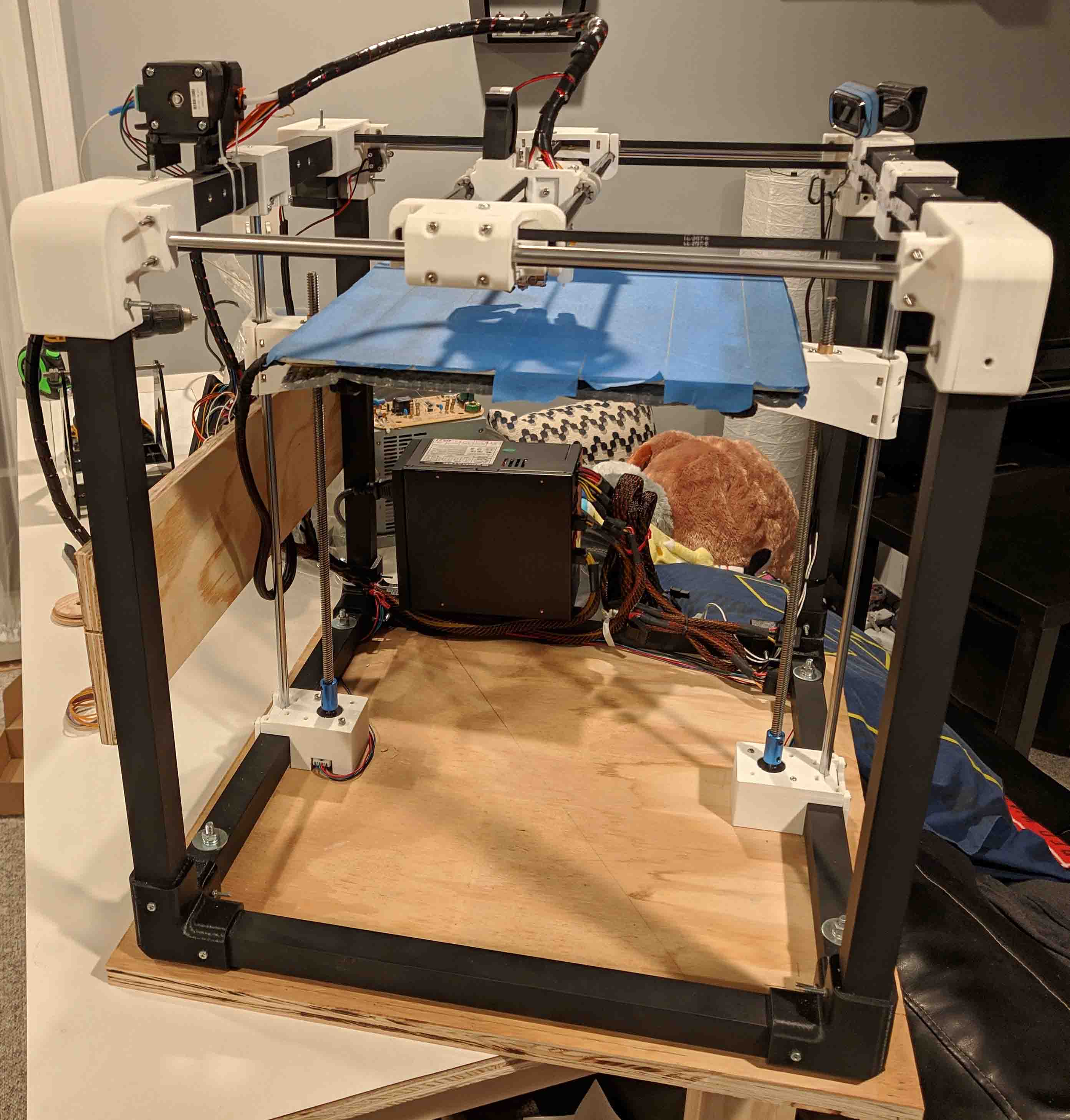
After my previous few experiences with building a 3D printer, I learned my lesson. Buy cheap, buy twice. I wanted this printer to be rigid, fast and durable. After doing some research and finding the pricey Voron, the HyperCube Evolution and a few others, I wanted a proven design so that I knew what I was getting myself into. I was told that the HyperCube Evolution was the way to go now that it had been updated to be fitted with linear rails instead of the old school rods that I had been using in the past. This lead me to find the HevORT. It takes from the HyperCube Evolution and builds on it. The HevORT is also a pricey machine so I opted to create my own mashup of the HevORT x/y system with the simpler Z axis of the HyperCube Evolution.

My CAD model of the Hevo/HevORT mashup I planned to build.
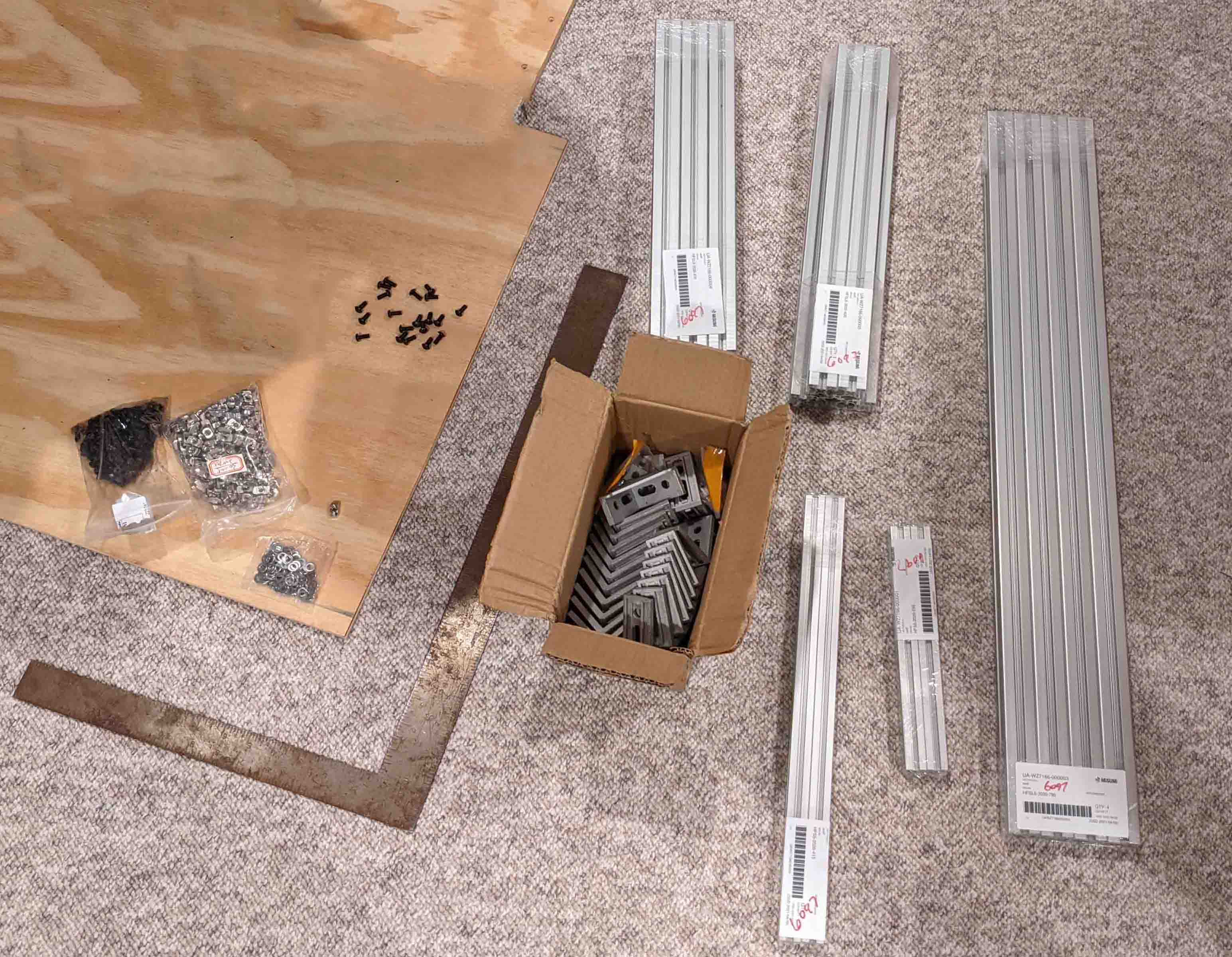
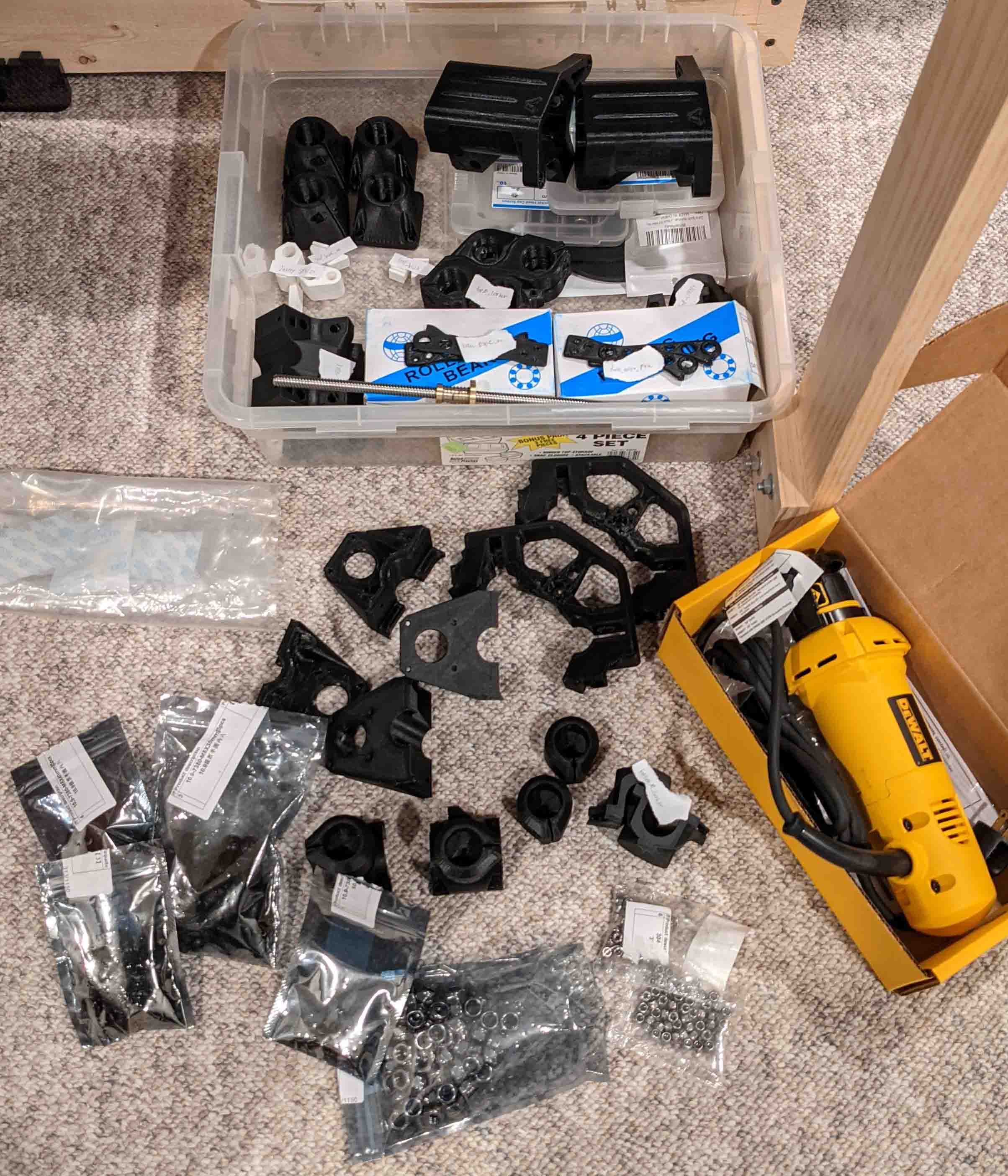
I found CAD models of each printer and threw the pieces I wanted to use together so that I could be confident that everything I ordered would fit, and that I'd have enough of everything. I spent an entire week sourcing components. It's difficult to find good prices on each item so a lot of time was spent mixing and matching until I found the best prices based on the combinations I came up with. It ended up being over 500 nuts and bolts, various aluminum extrusions, brackets, motors, bearings, hotend components, and electronics.

During the build process, I learned how to disassemble the linear bearings and clean the ball bearings (a must with cheap bearings). This painstaking process involves dealing with hundreds of 3/32" ball bearings that love to go everywhere!
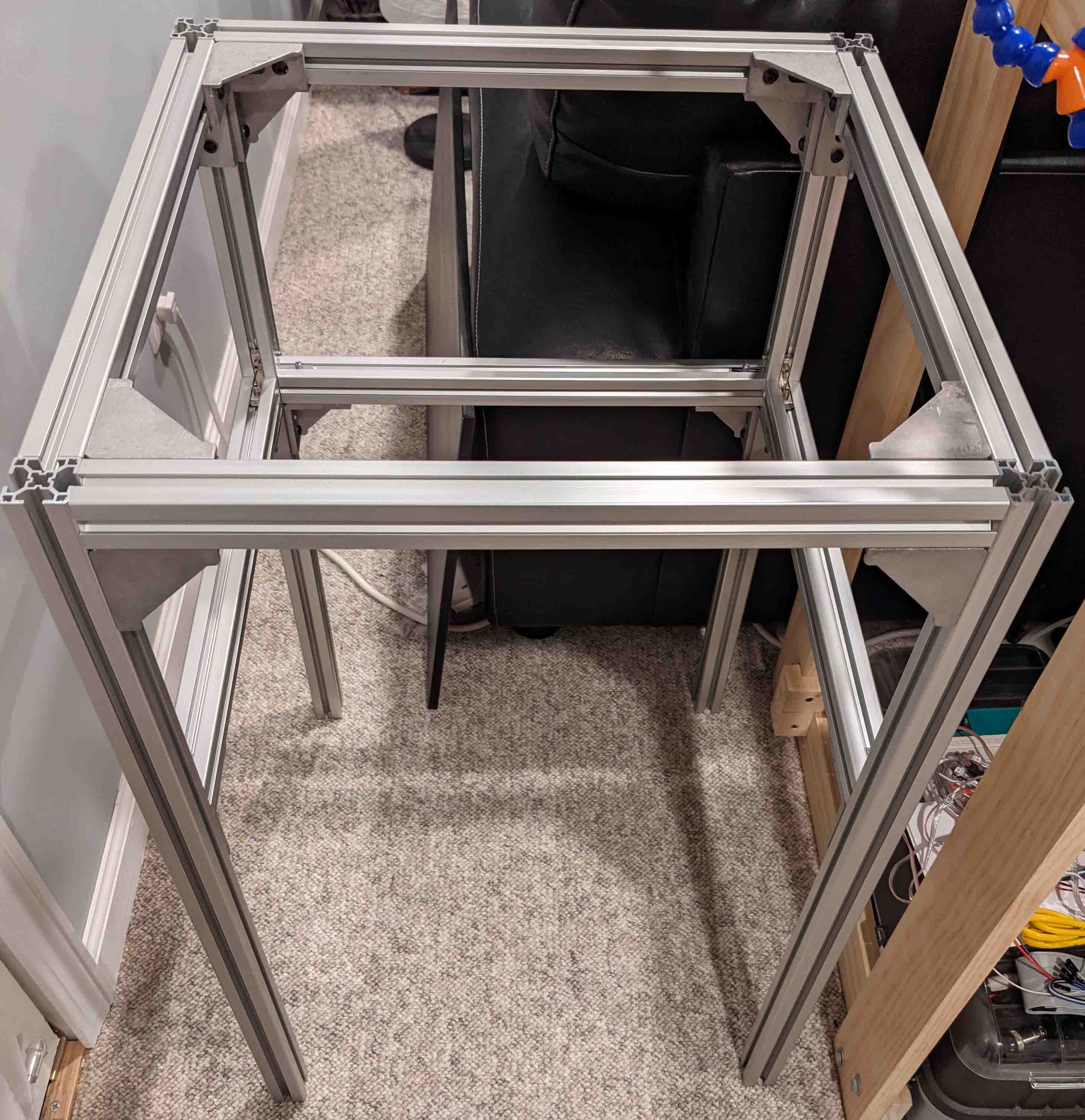
The frame and other components of the printer went together with relative ease. I ended up with the sturdy and quick printer I was hoping for! I call it the "HevORT-C" since it's a cheaper version of the HevORT.

Corvette Engine Modifications
Forewarning, if you aren't into cars, this project probably won't seem very interesting. If you are, prepare for awesomeness.
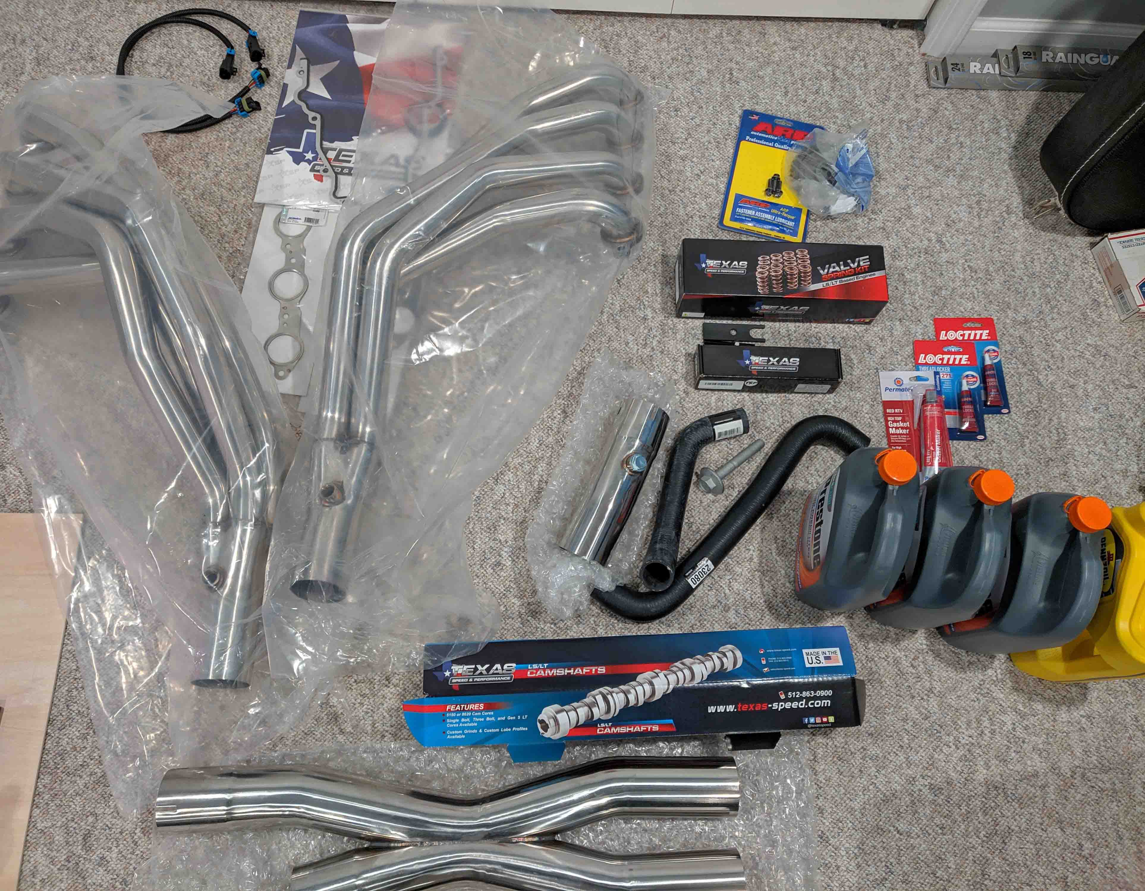
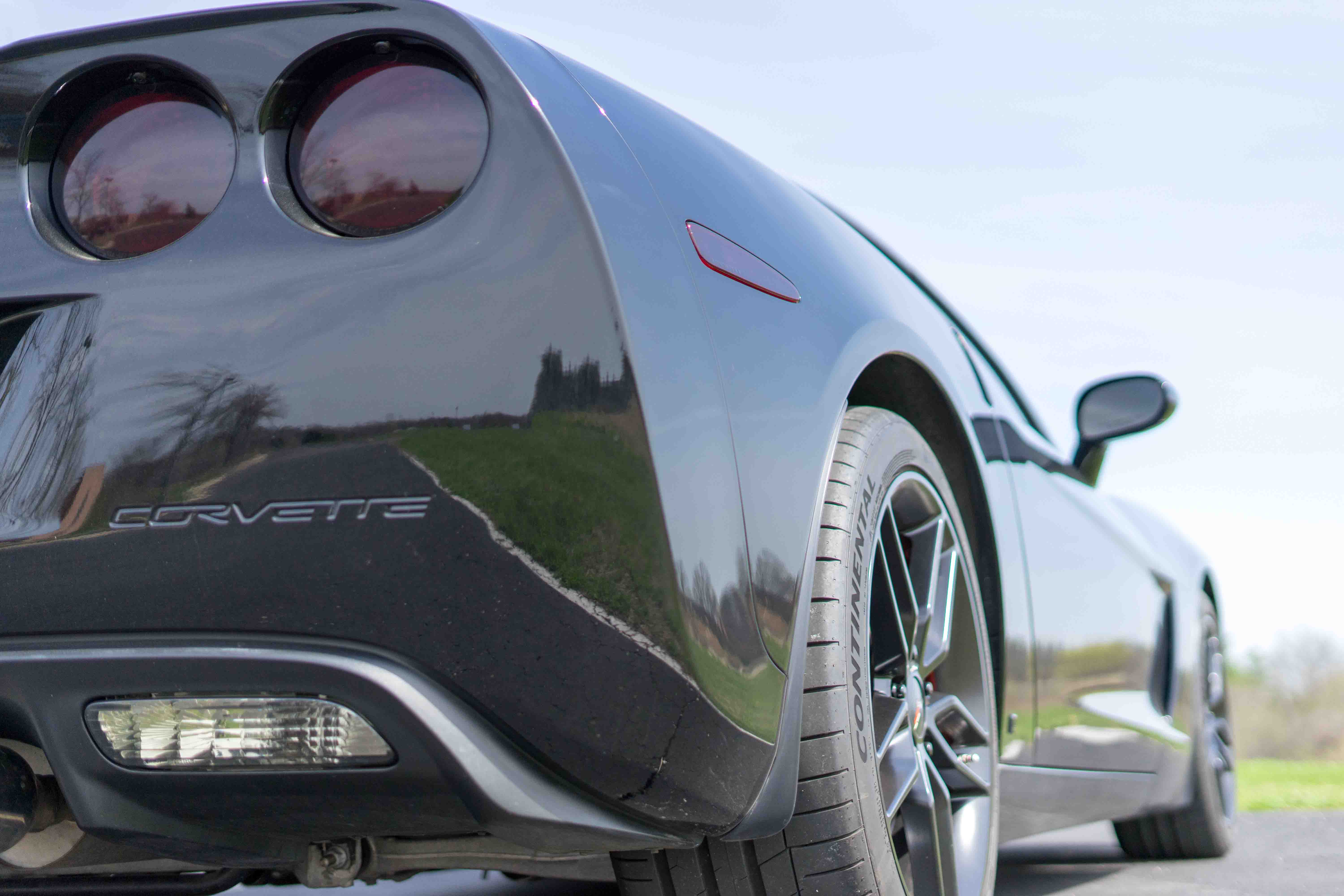
While I was growing up, my dad had a 1967 Corvette so I've always been interested in cars. I absolutely love the way the C6 body style looks (2005-2013 Corvette). I ultimately wanted to buy a C6 ZO6 but the used prices just didn't make much sense so I bought a base C6. Since I was so used to the rumbly sound of my dad's corvette, I wanted to install an aggressive camshaft in mine so that I had a similar sound (and more power!). If you install a cam, you might as well install long tube headers too since they net you another 30ish horsepower with the LS3.
I ended up buying a Texas Speed stage 2 LS3 cam kit and a set of long tube headers from Speed Engineering. It's probably a good thing I didn't realize how much work it would be when I bought the parts. This turned out to be a month long process, but it was very rewarding to be able to do it in my own garage with my dad.
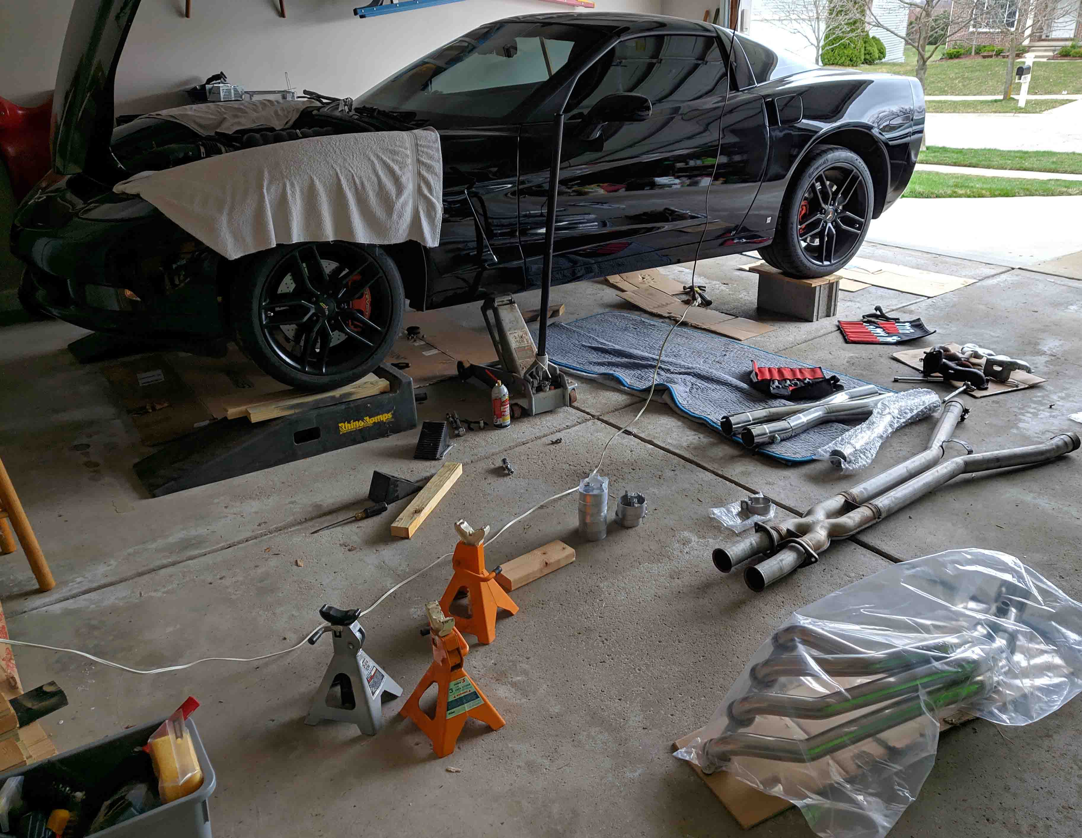
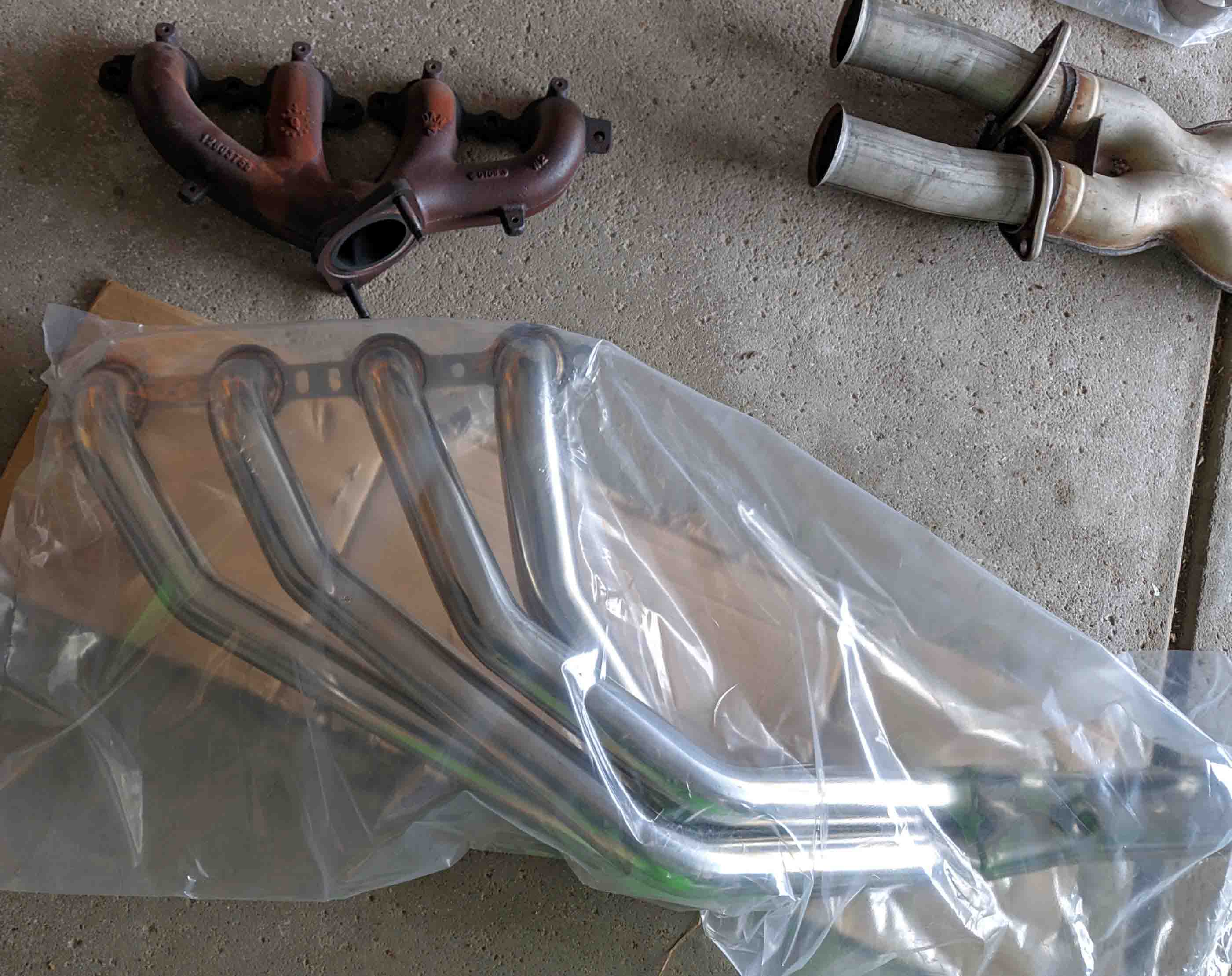
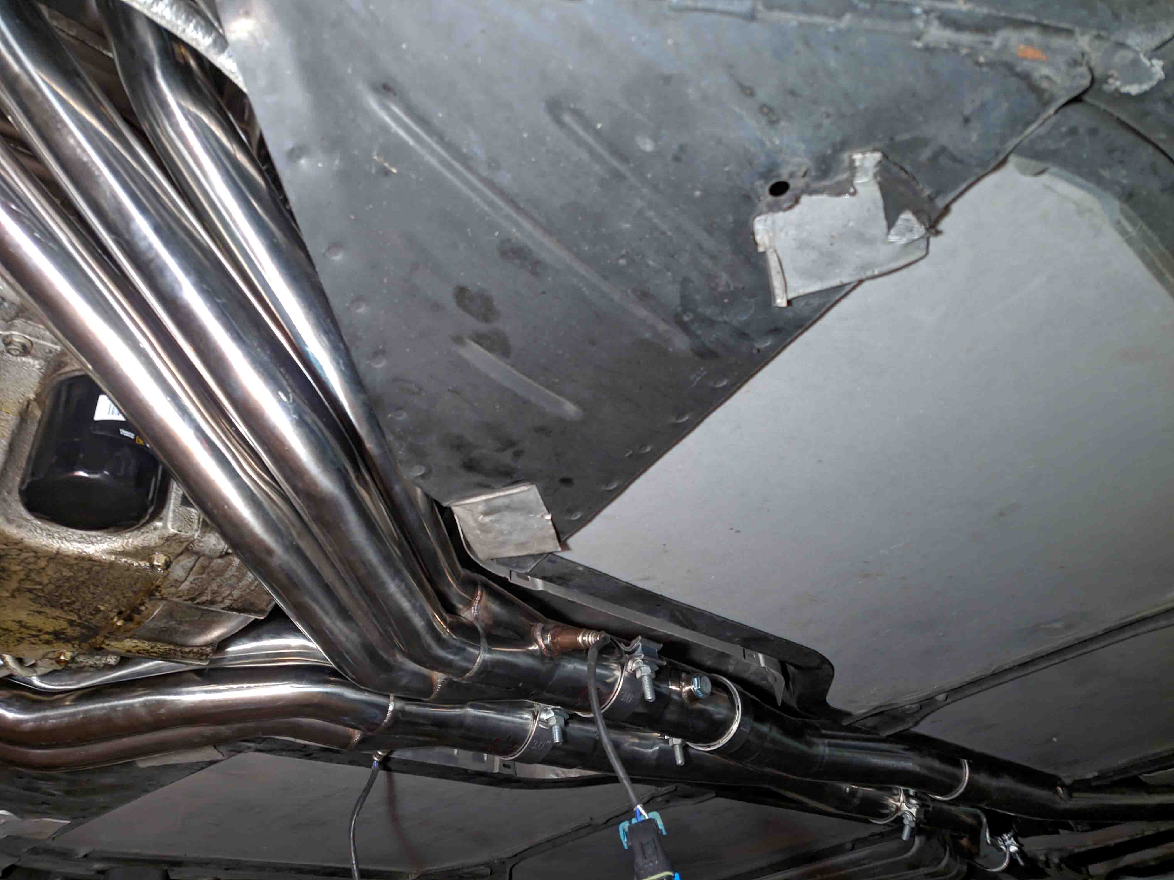
First I tackled the exhaust system. I uninstalled the stock short tube headers and fitted the long tube headers. The hardest part of this was getting everything beyond the headers to fit together correctly since there wasn't much room for error.
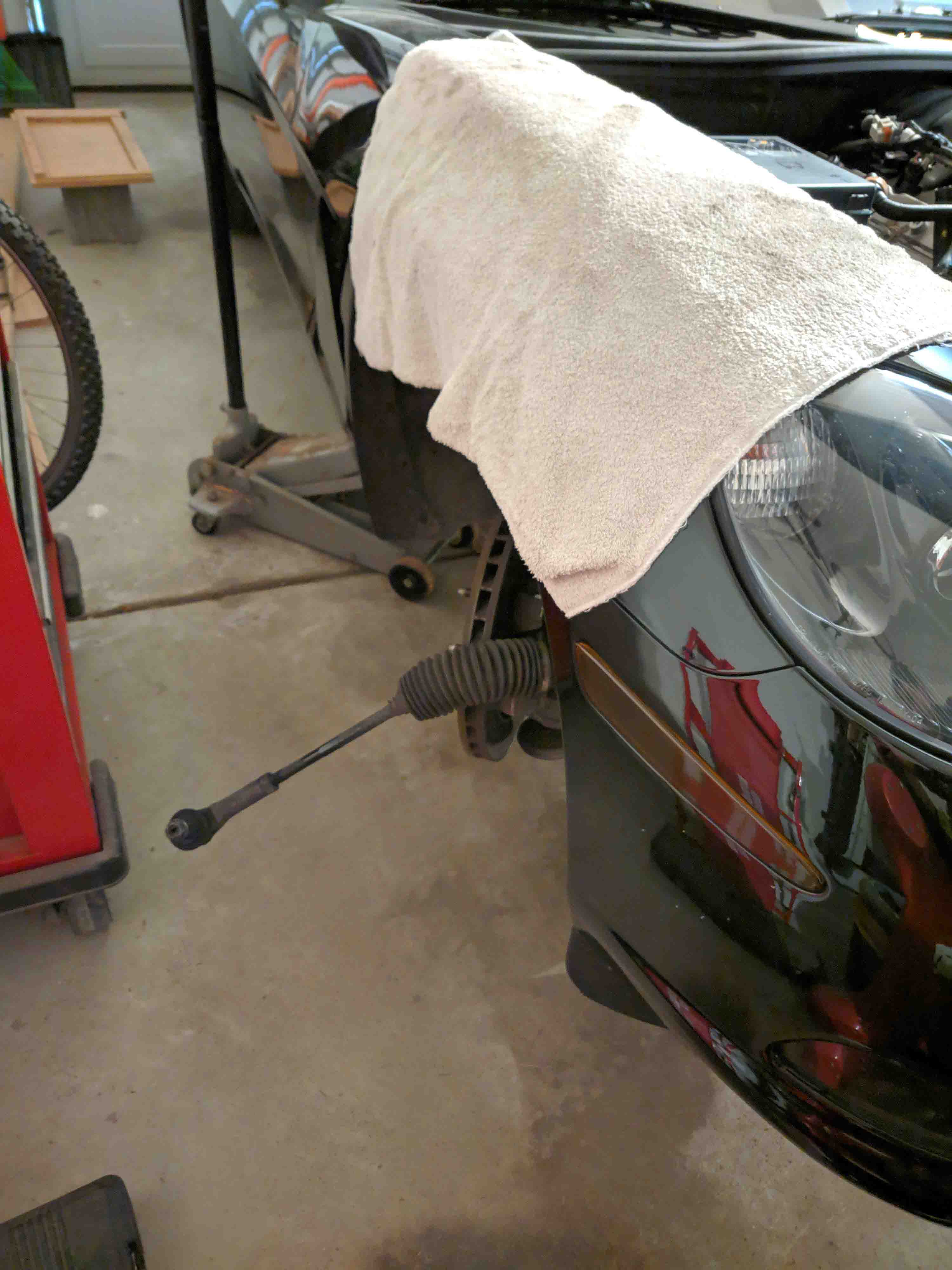
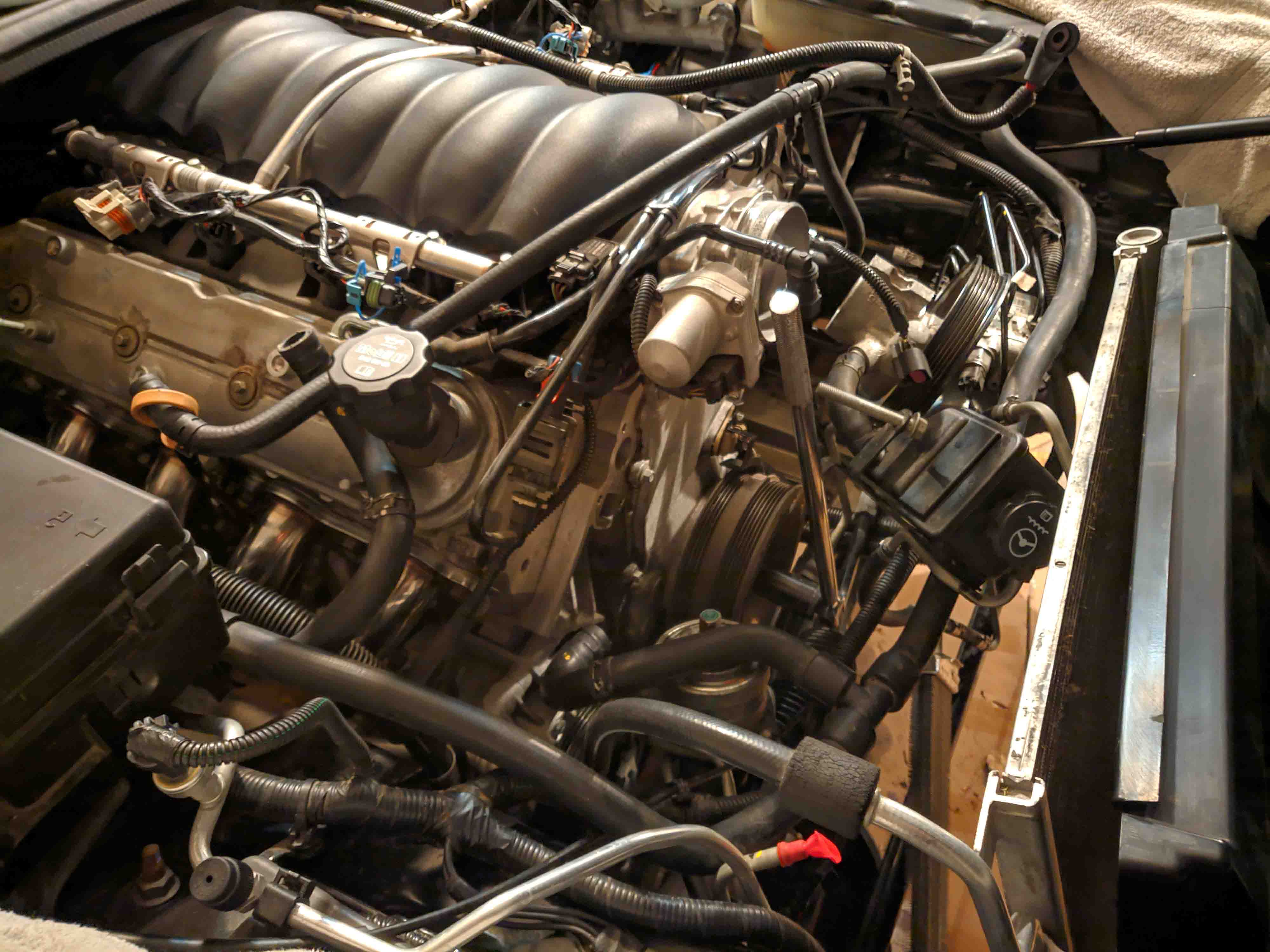
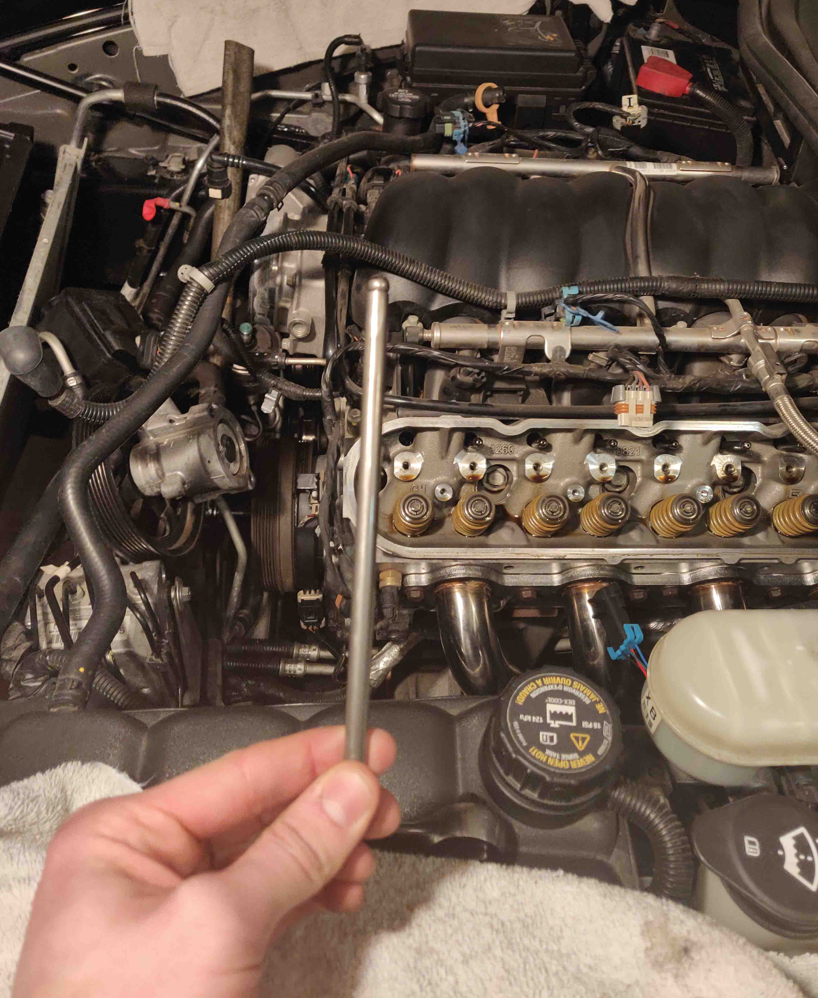
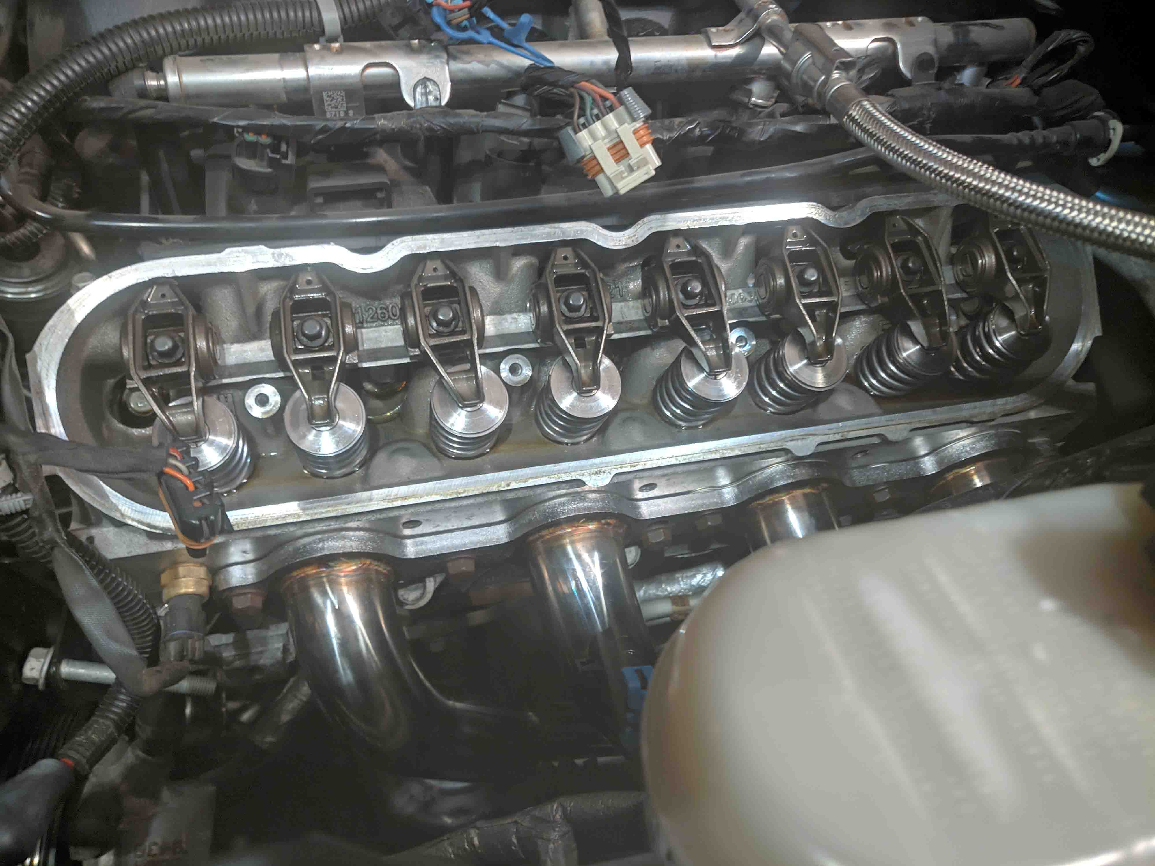
After the exhaust, I moved onto the much scarier task of opening my engine and swapping the cam. One of the unfortunate things about the C6 is that the steering rack sits in front of the engine. This means that you have to almost completely uninstall the steering rack and push it out of the passenger side of the car to get enough room to uninstall the harmonic balancer. I skip over a lot of steps before the next set of pictures, but the radiator, alternator, water pump and power steering pump all had to come off of the front of the engine. The valve springs, rockers and push rods had to be removed. I also had to remove the starter motor and install a flywheel lock so it was possible to remove the crank pulley bolt.
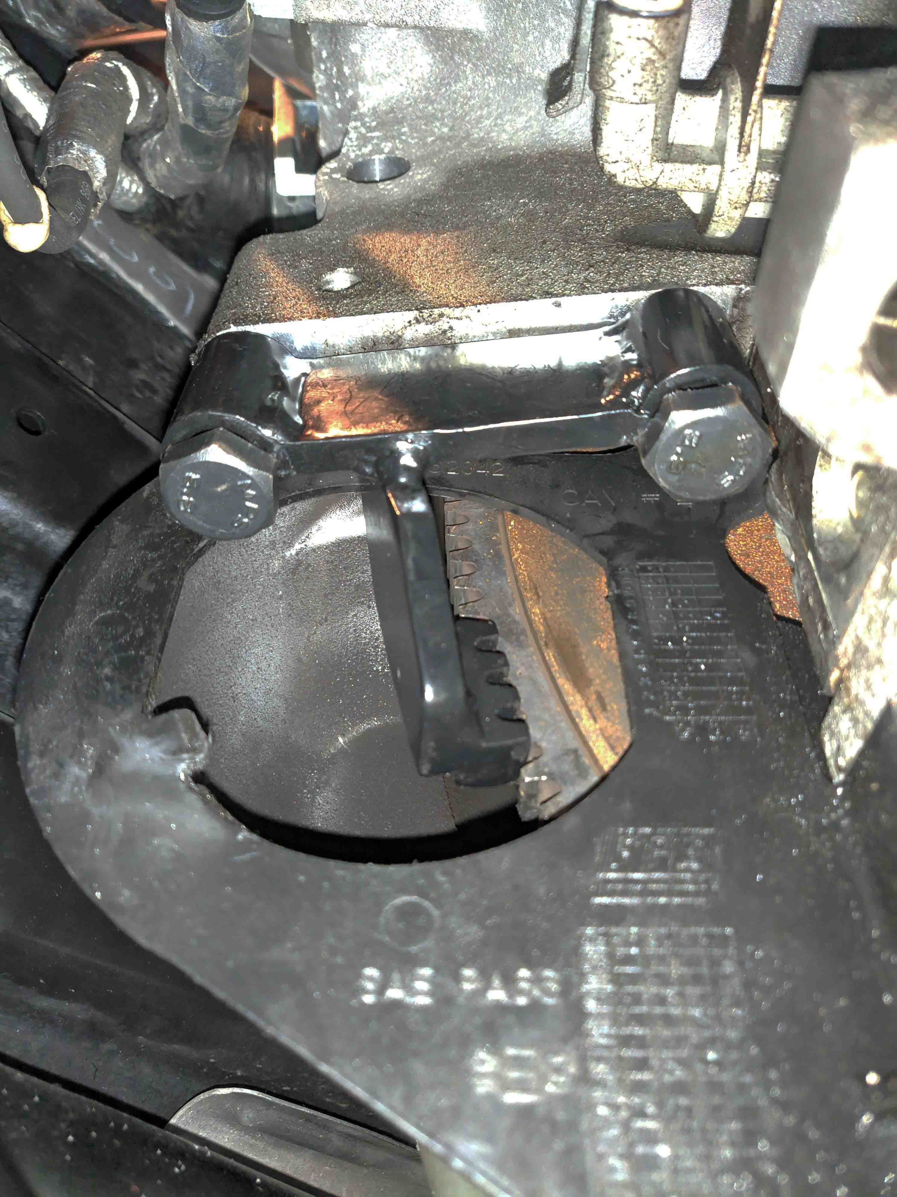
After all of that work, it's finally possible to remove the timing cover and get to the camshaft. Comparing the new and old camshafts, you really couldn't see much of a difference in terms of lobe size or shape.
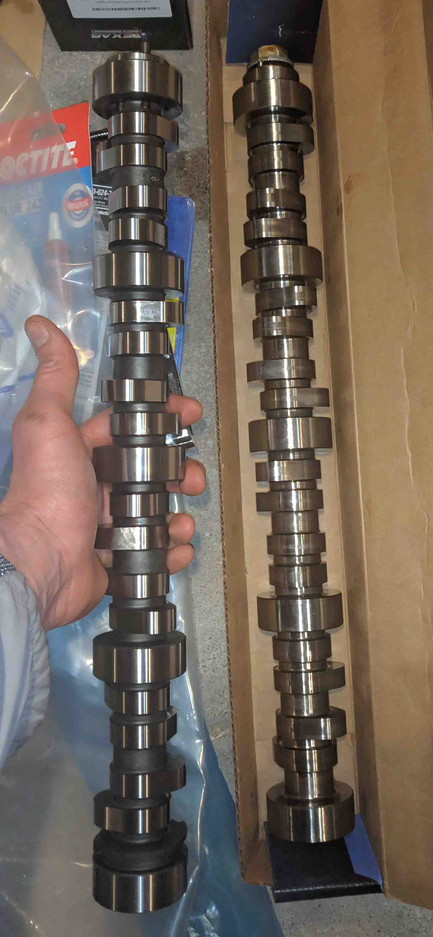
New camshaft on the left, stock on the right.
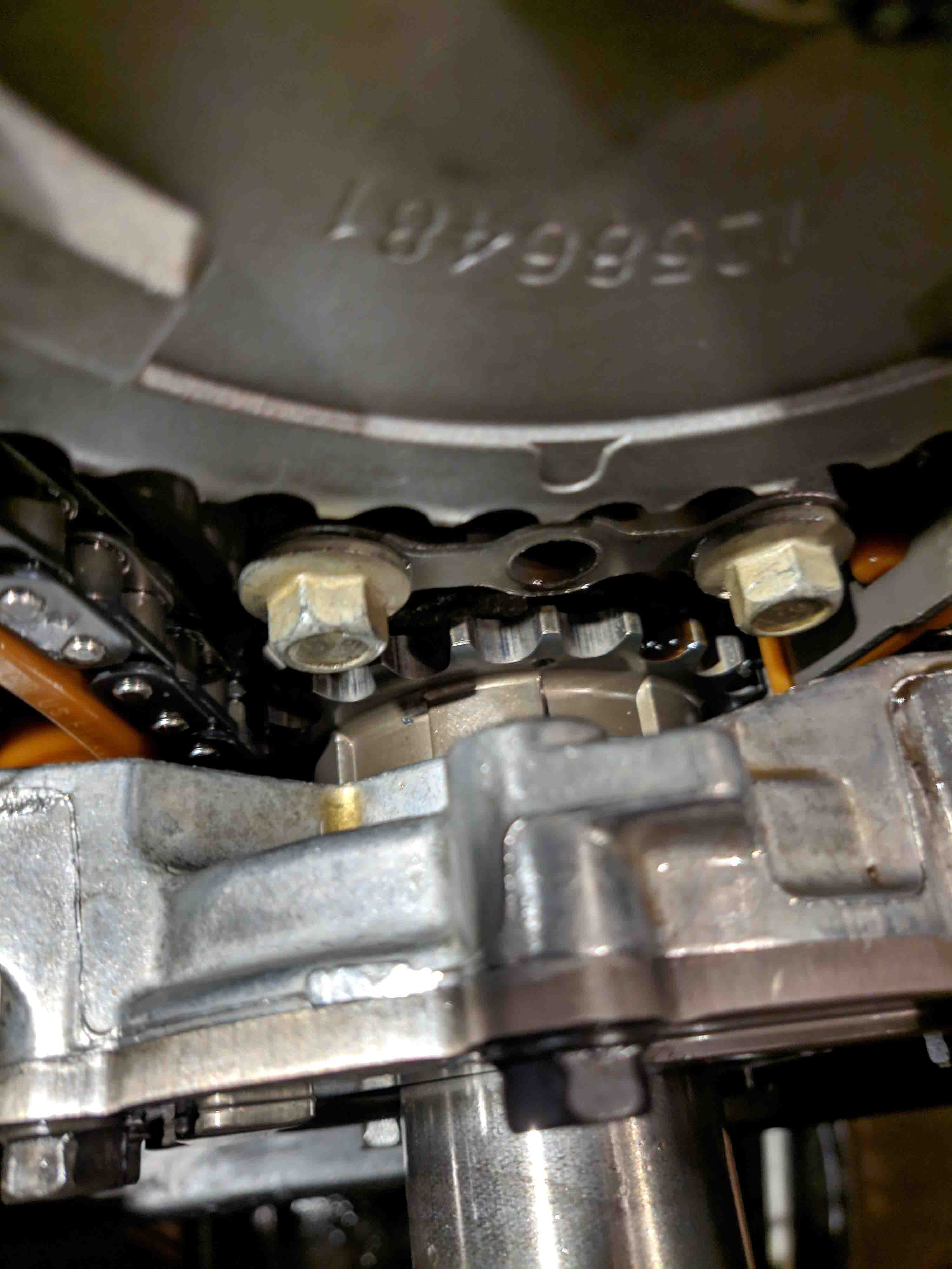
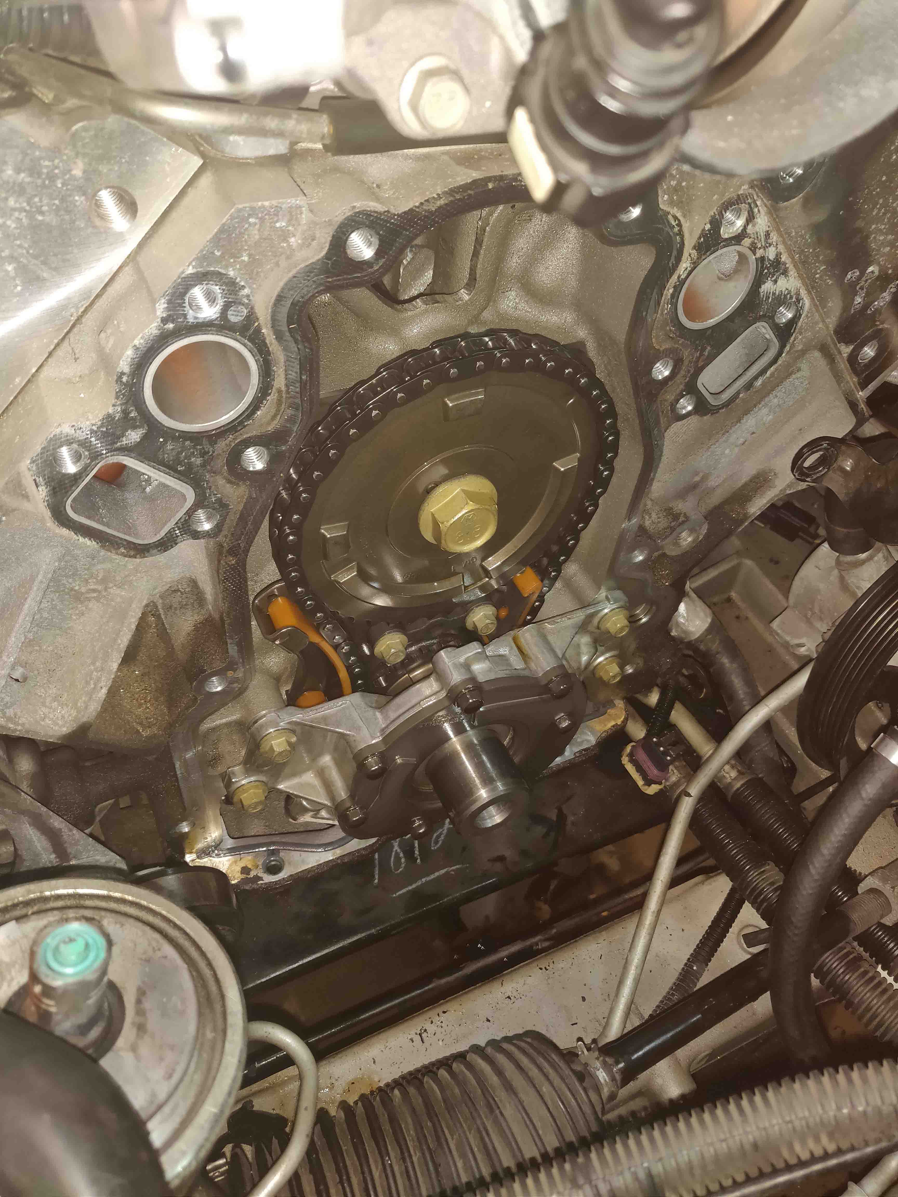
Now the process of reassembly. I was very careful to set the timing correctly. It's a little nerve-racking to trust the little dots on the gears but everything ended up being ok.
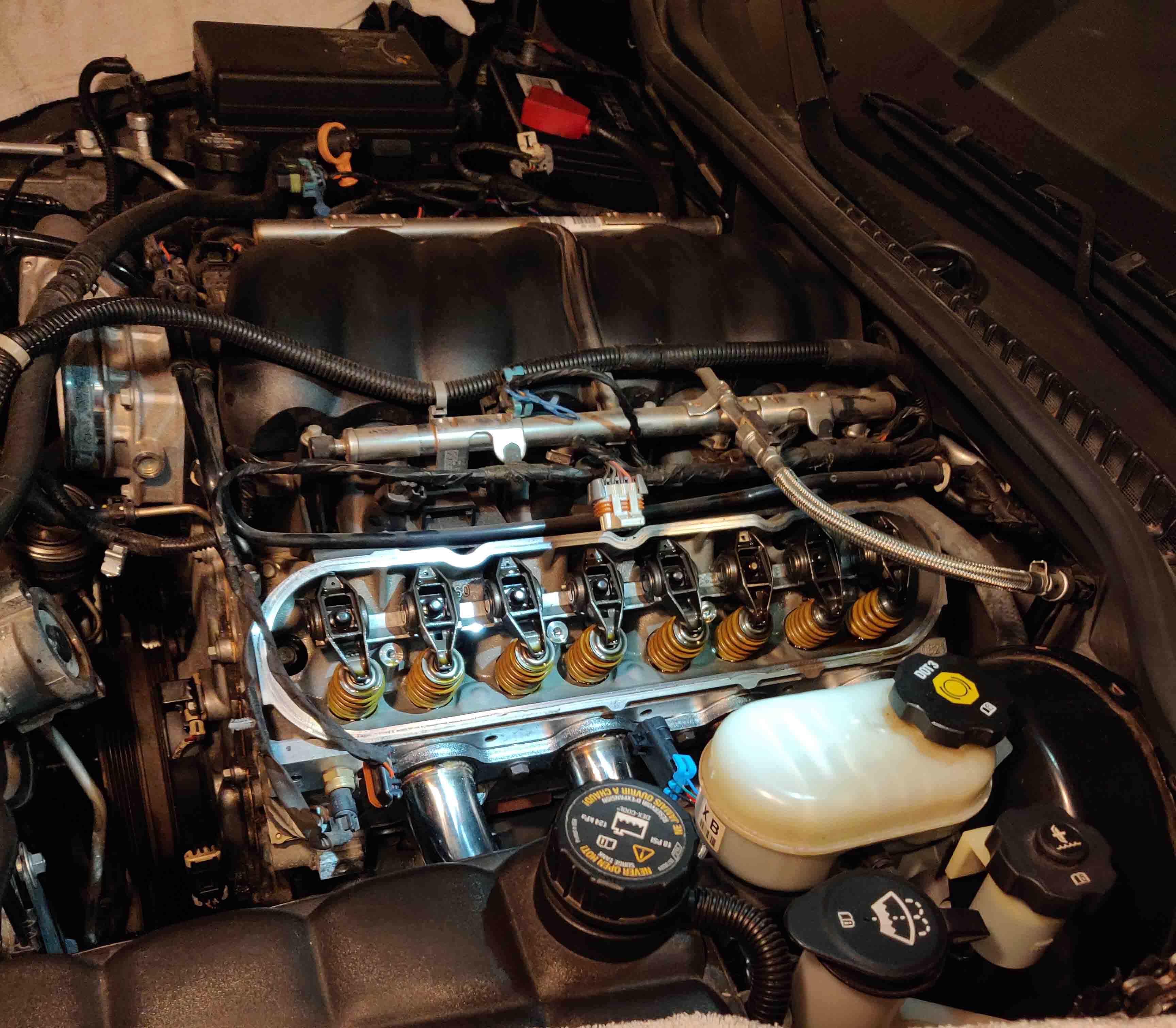
I removed the old valve springs and seats and replaced them with the new, much stiffer springs.
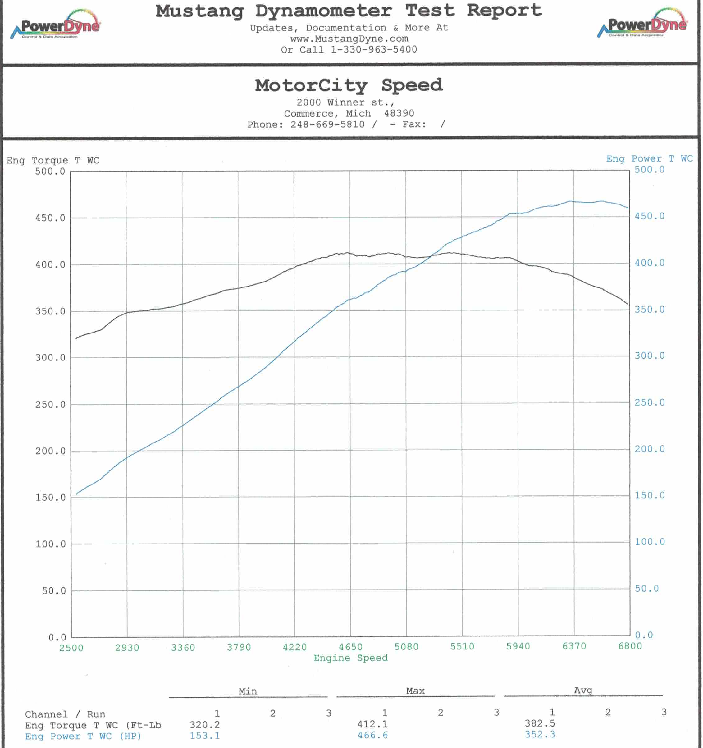
After reinstalling everything else, I finally got to start the car. Surprisingly it started up on the first shot (and sounded amazing). I had it dyno tuned since the new parts required that to run properly. Unfortunately I didn't have it dyno tested before installing the parts but stock LS3 powered C6 Corvettes make about 370 peak horsepower to the rear tires. Mine dynoed at 466, almost 100 horsepower more than stock!
I still own the car and enjoy driving it when I get the chance to.

MPCNC
It's probably pretty clear by now that I like 3D printers. I wanted to give CNC routing a try since they are very similar. I found the MPCNC project and decided to give it a try. This project is enticing because MPCNC means "mostly printed cnc" meaning it's mostly 3D printed parts and electrical conduit. I sourced all of the nuts/bolts, electronics and printed all of the parts to assemble the MPCNC.
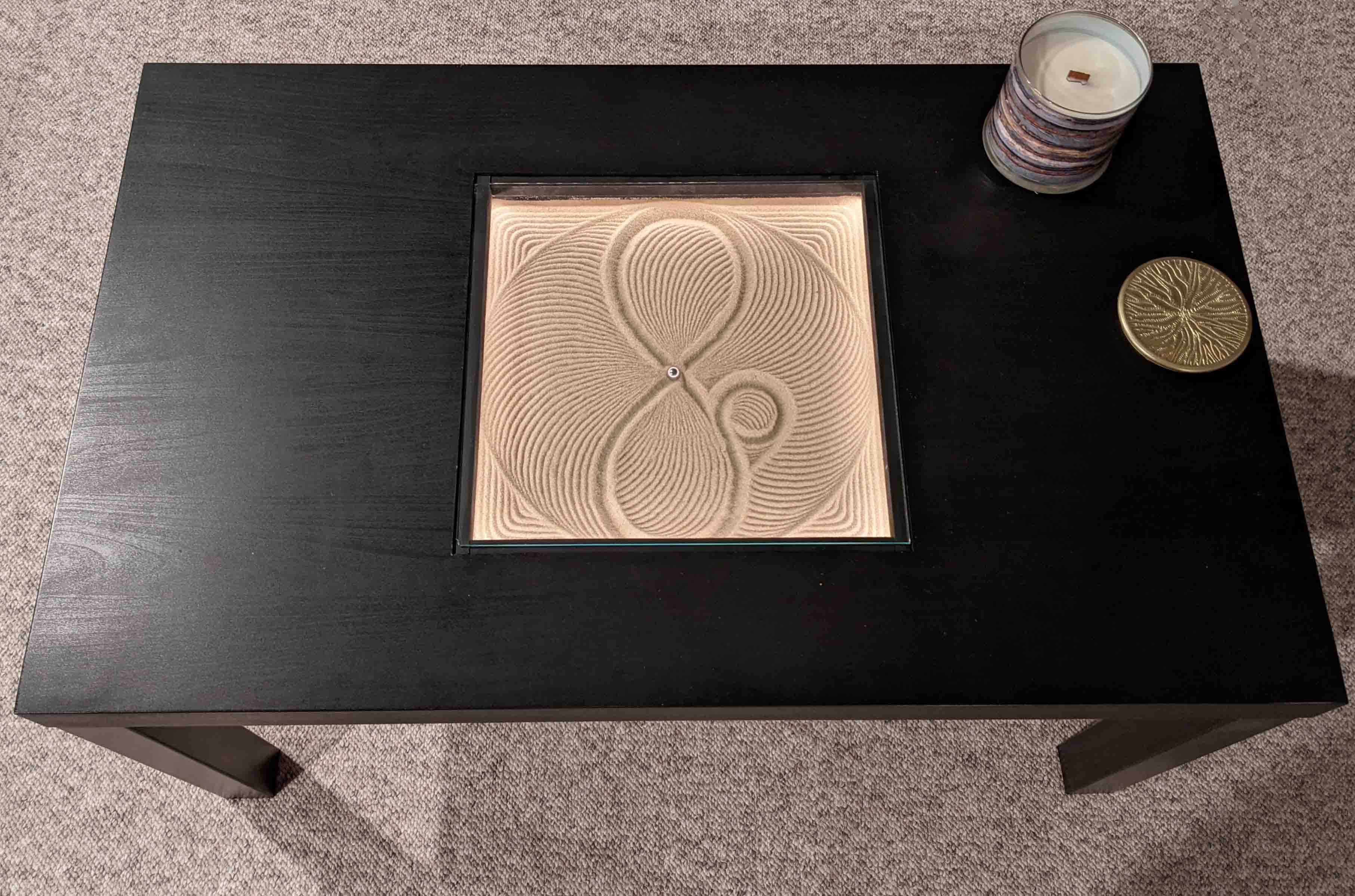
Sand Table
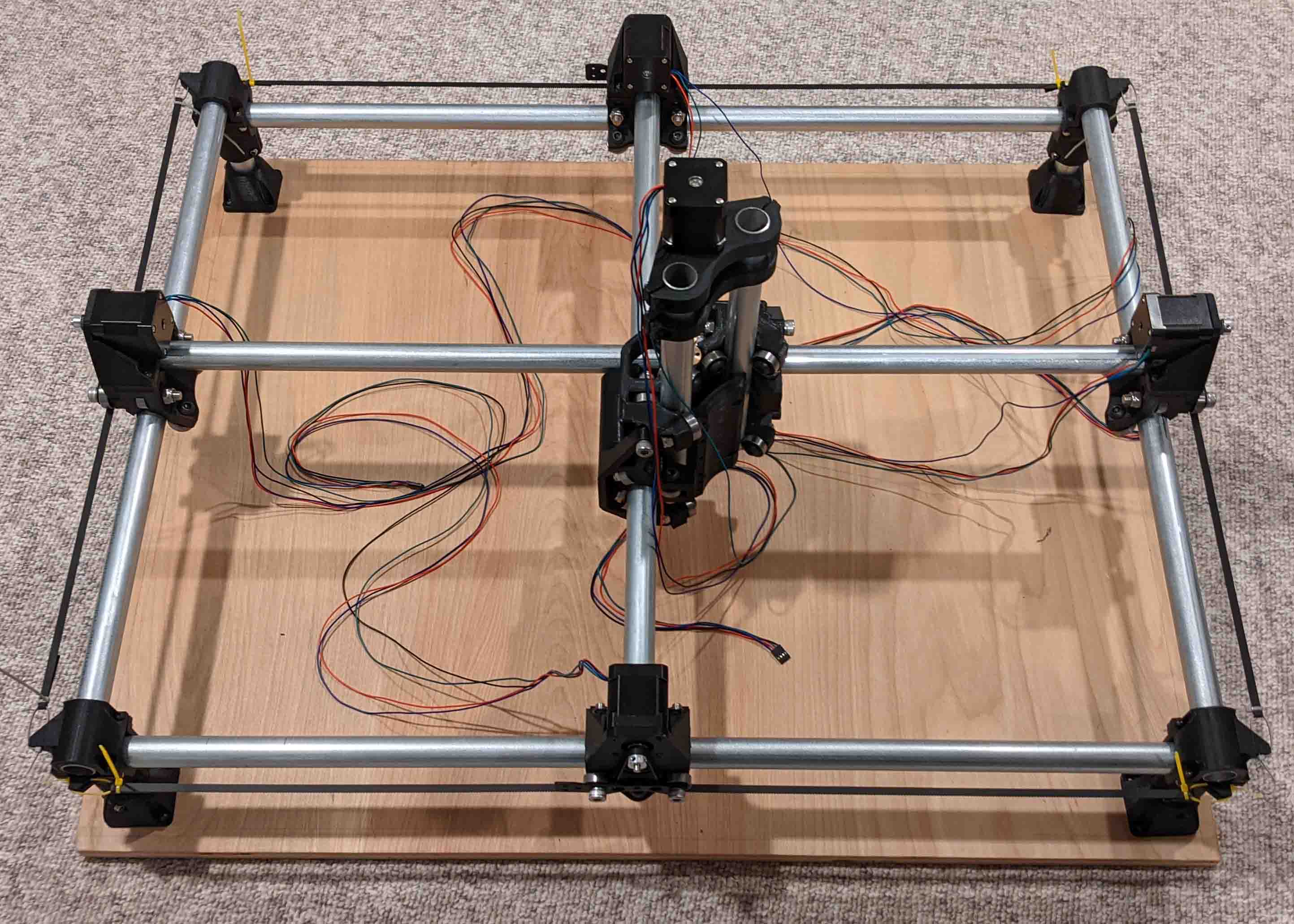
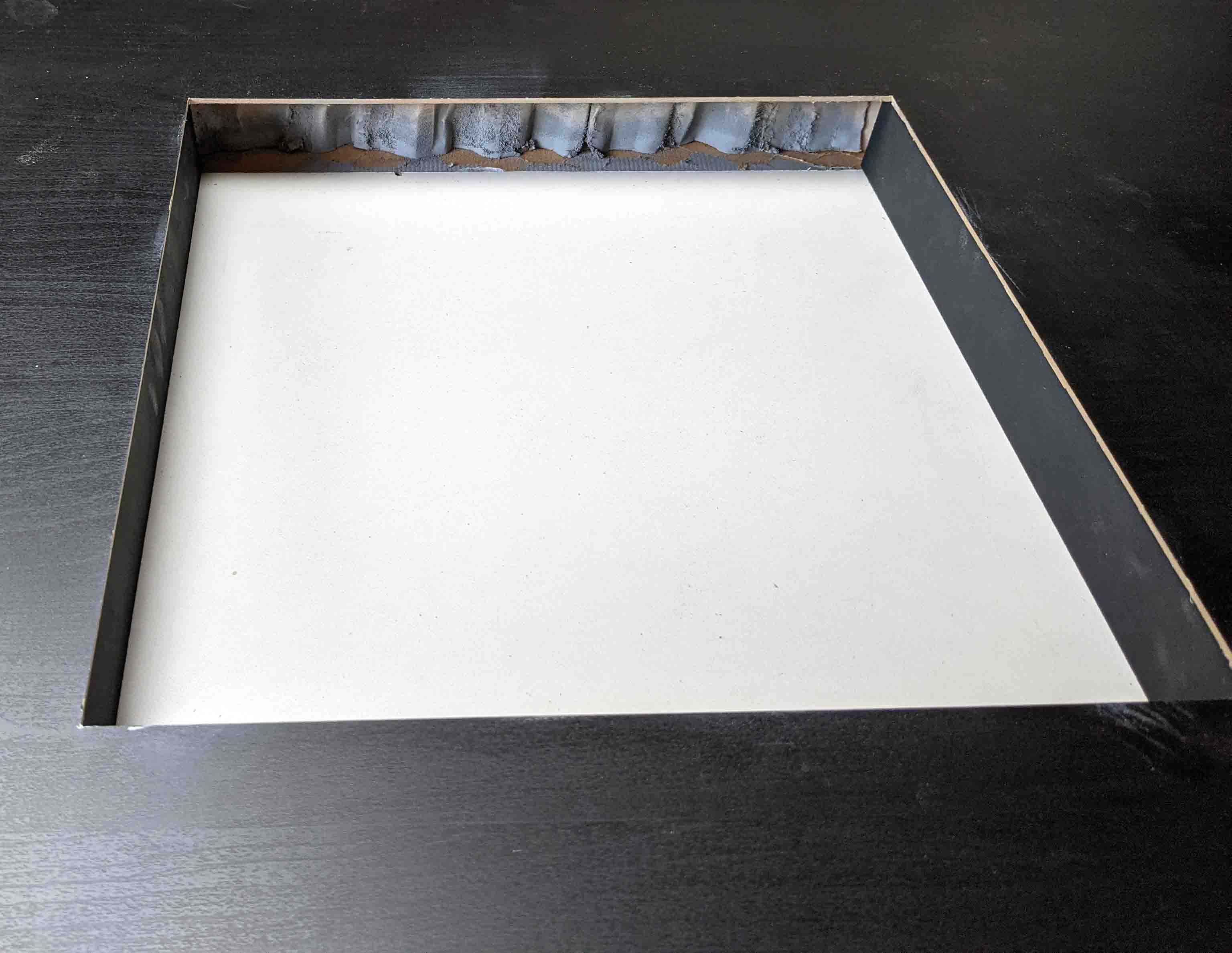
For this project, I was inspired by the Sisyphus table. It's essentially a table that has a computer controlled magnet mounted under the table top with a ball bearing. It draws neat patterns into sand. I stumbled upon an open source version called the ZenXY and decided to put my own spin on it. Since I had the X/Y gantry from the 3D printer that I scrapped, it seemed like a perfect fit for this project since the ZenXY is essentially a 3D printer with no Z axis. I also saw a few ZenXY builds that used Ikea tables since they're hollow inside. It makes it really easy to build a "sand tank" into the table. I started by routing a square piece out of the top of the table and tearing out the carboard support inside. I had to glue in a piece of formica because the bottom wasn't flat and was impossible to sand flat.
I cut up some scrap MDF to frame in the sand tank. I mounted the X/Y gantry to the bottom of the table and designed a simple magnet holder to fit on the old 3D print head. I also drilled a hole into the sand tank frame and fed some wires through for some LEDs. Gotta have that RGB!

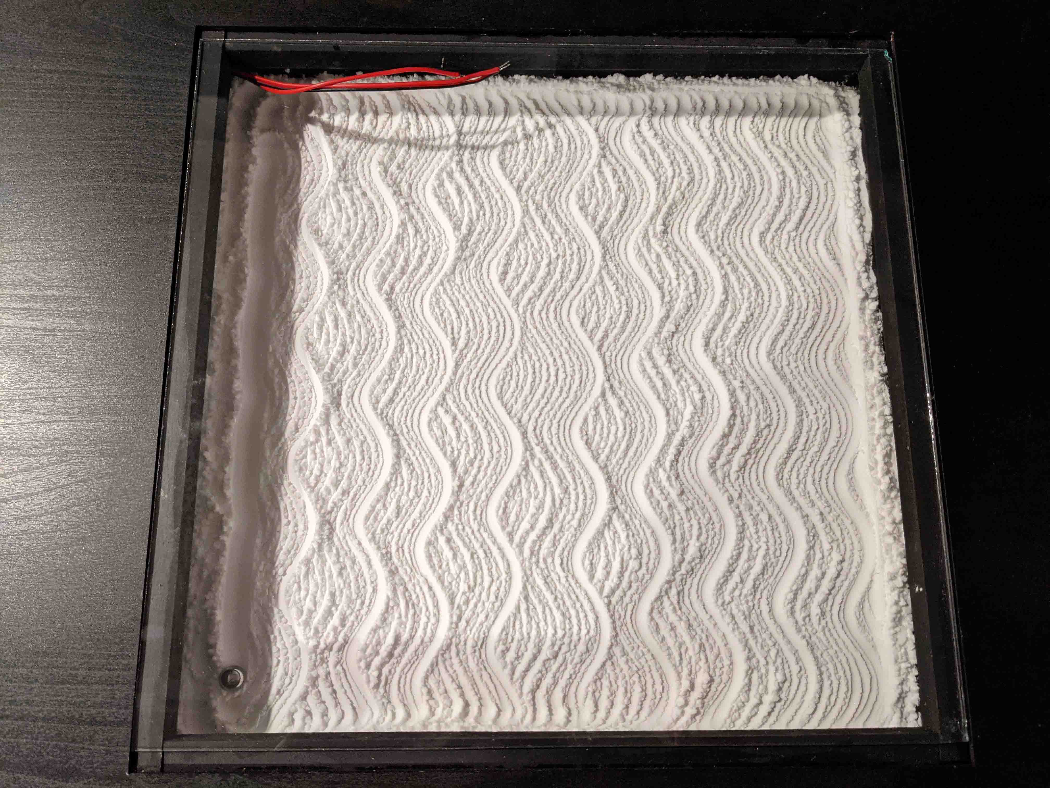
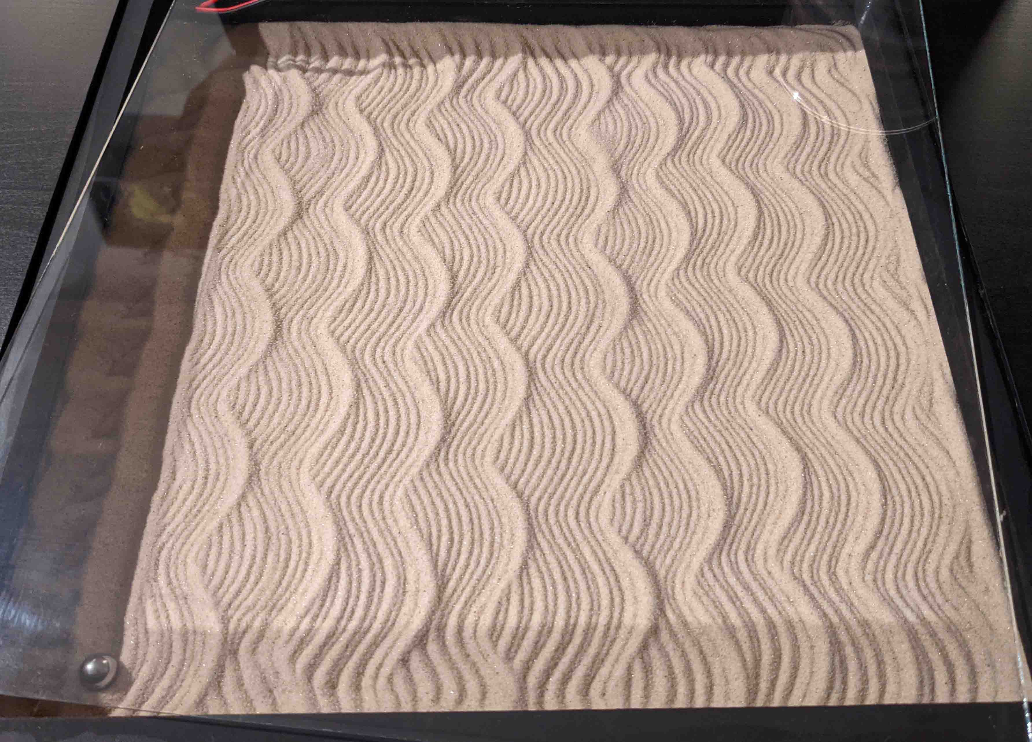
Initially I tried using baking soda as the drawing medium because sand made an awful crunching sound when the ball bearing rolled around the table. I was never satisfied with the baking soda because it ended up clumping together and overall lacked the texture that sand has. I discovered that using a really thin rubber mat cut the sound to a very tollerable level and moved forward with using sand. The natural sparkle that sand has really stands out. You can see the difference below. Baking soda on the left (first), sand on the right (second).
Finally I installed the SK6812 RGBW LEDs. They really took it to the next level.
Example of the table in operation - sped up by 5x
DIY Speakers
I've always enjoyed listening to music and have been curious about speaker design. I came across a video by HexiBase that really caught my attention. 3D printed speaker enclosures! I wanted to give this a try since it was relatively cheap and I loved the idea. I used HexiBase's design but decided to put my own spin on it.
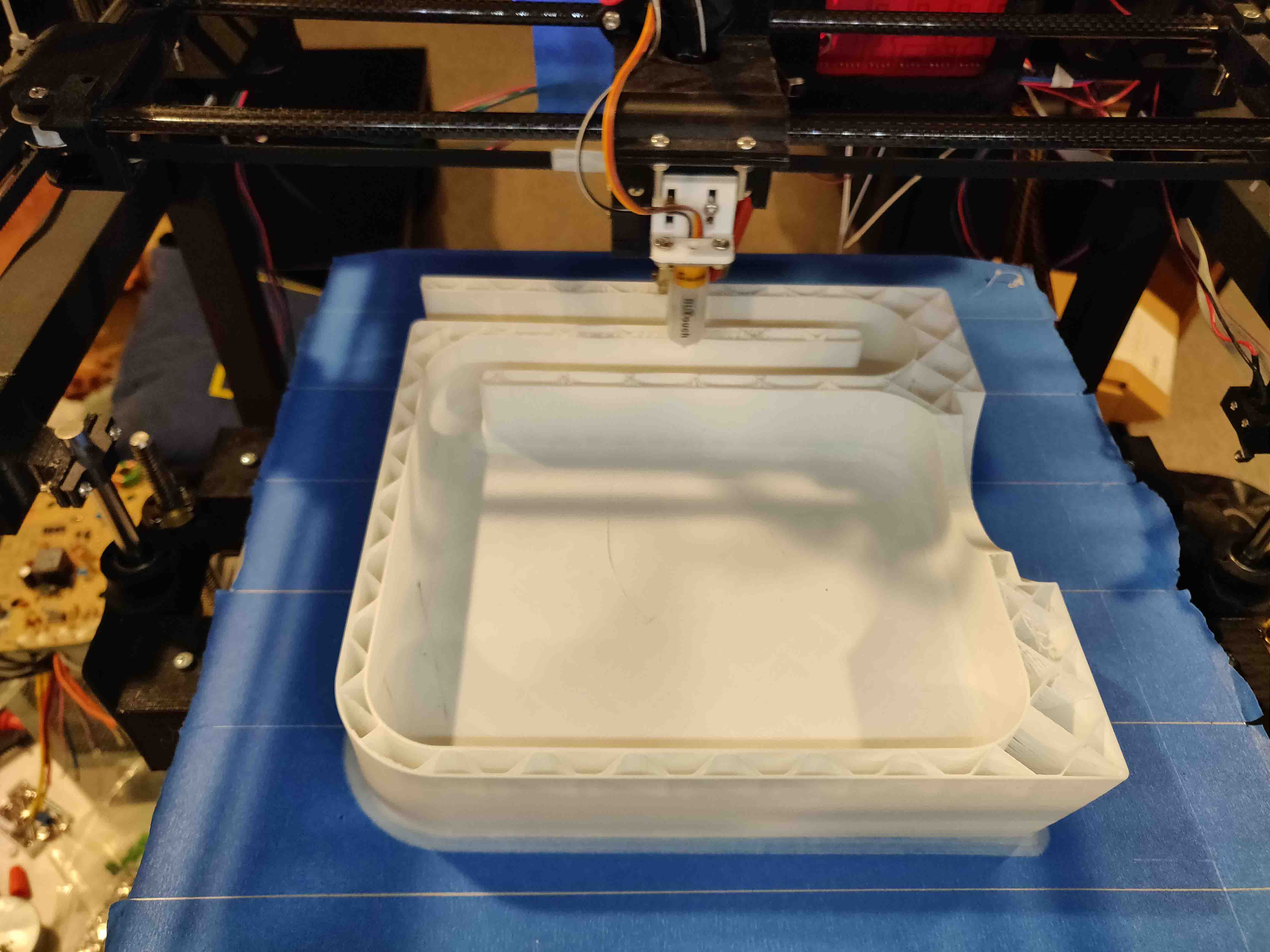
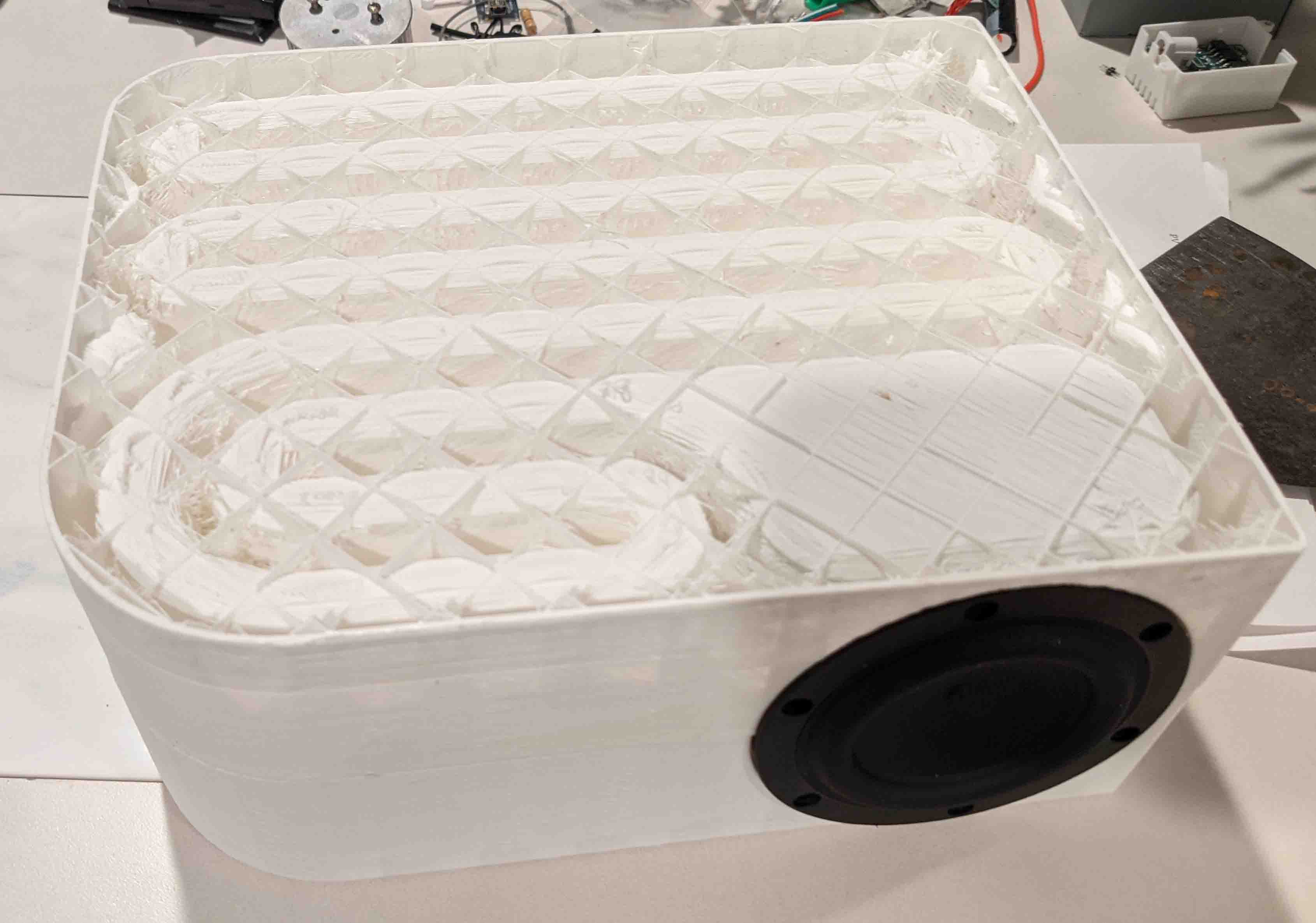
Printing the HexiBase bookshelf speaker.
When HexiBase printed his out, he used a lot of filament (and time) to achieve the infill amount he desired. At the time, my printer wasn't great so I worried about prints that exceeded 8 hours. So, I thought, why not fill it with concrete instead of plastic? I printed the speaker halves with 0 bottom layers to make it possible to pour concrete. Once the print finished, I flipped it over and tore as much of the infill out as I could to make it easier to pour into. I used sanded grout and filled each half separately and then joined them with adhesive caulk and painted the white plastic with black spray paint.
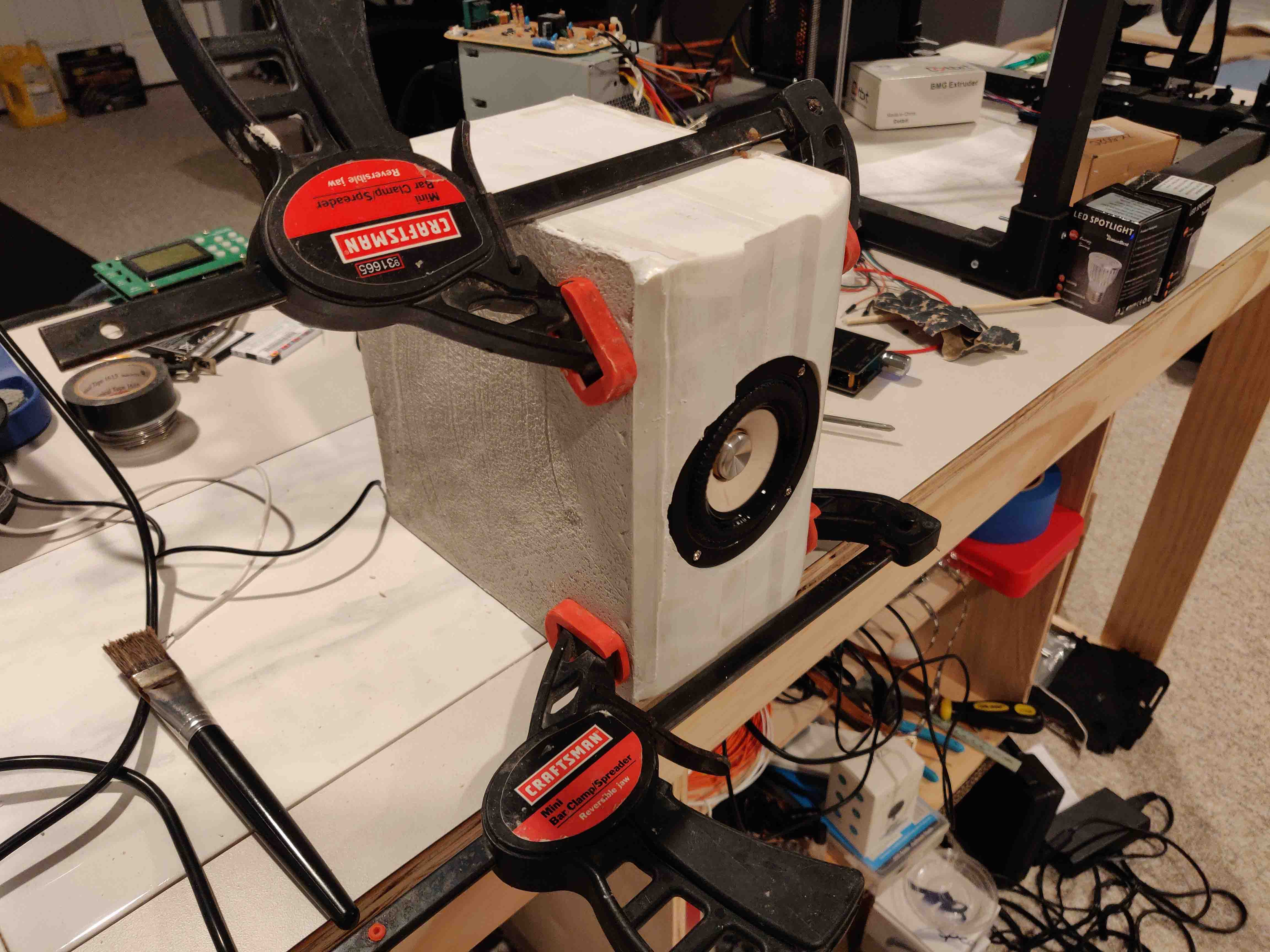
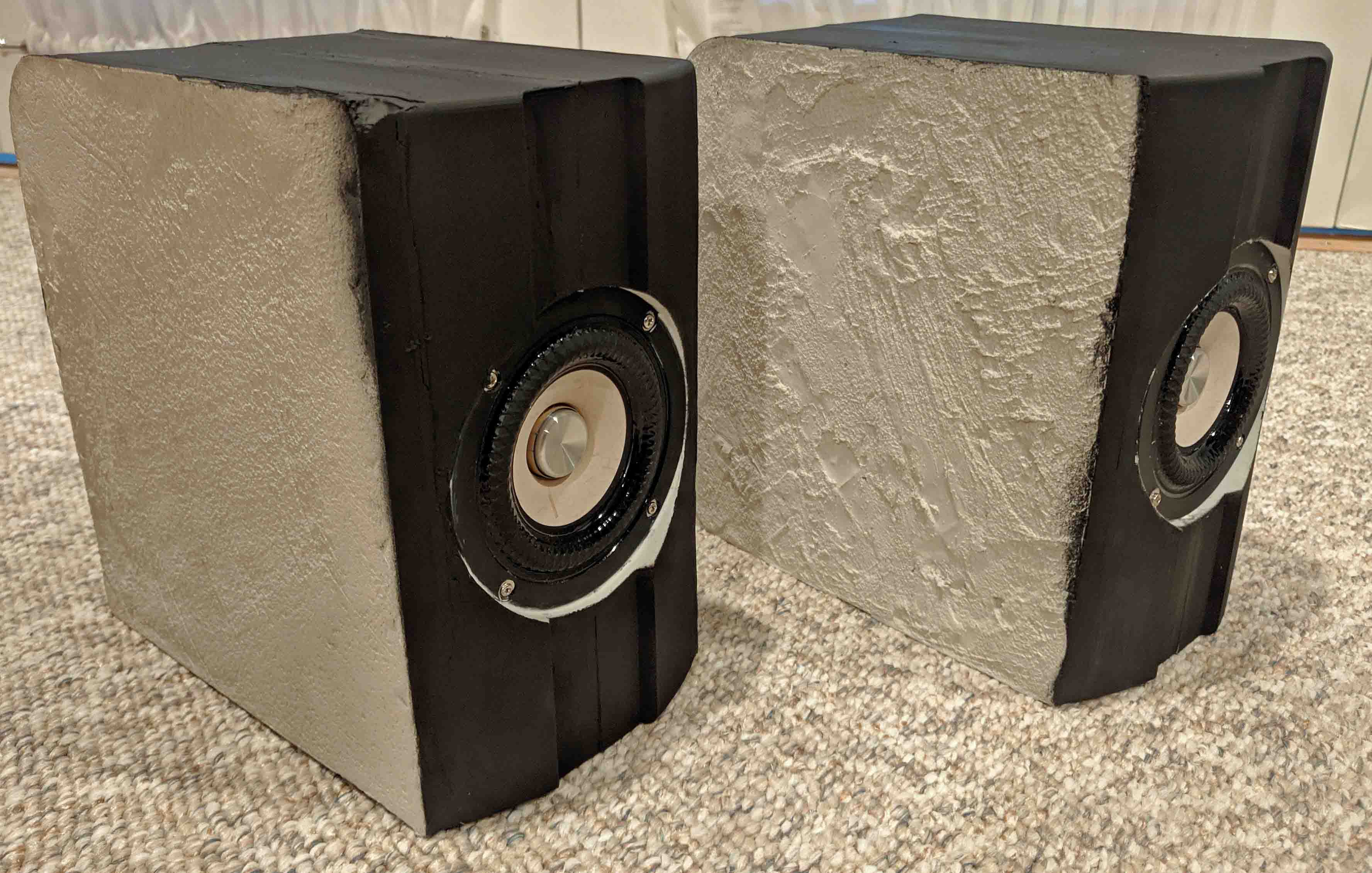
When I tried them out I was blown away by the sound, especially for their size and cost. Since HexiBase also had a mini subwoofer I decided to build that too. I used the same technique of filling it with sanded grout.
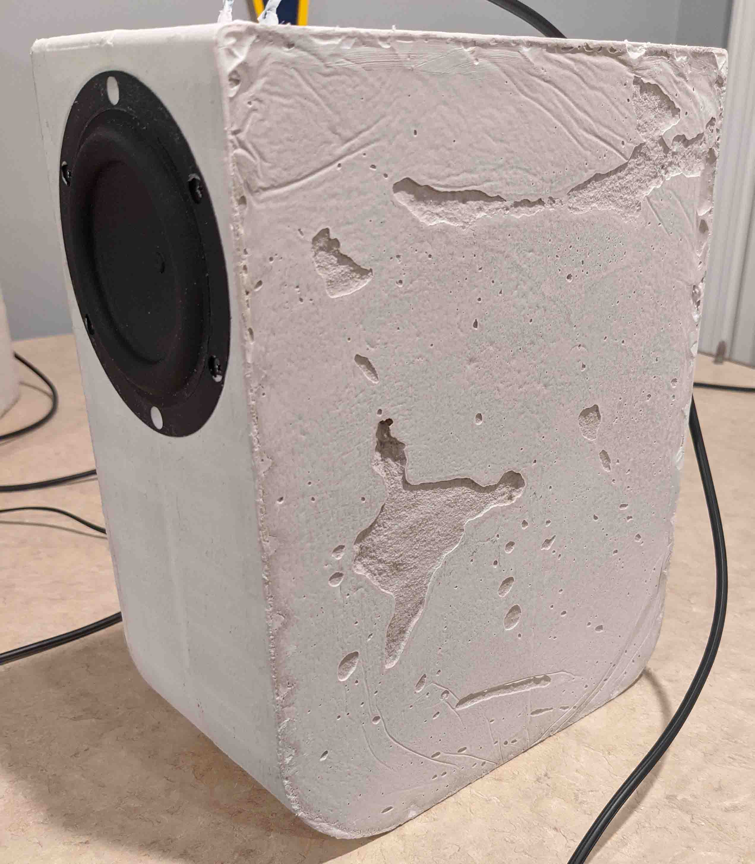
Again, I was blown away with how a tiny 3" subwoofer driver created room filling bass! This eventually lead me on to attempt a large subwoofer build with MDF. I found a design for a subwoofer that played low but not extremely loud. Since the design was created with europe in mind, I had to lay it out in CAD and make sure the dimensions lined up with the MDF sizes we have here. After completion, the big subwoofer can punch down to a room shaking 21hz before being out of its range.

Christmas Lights
Since I consider myself to be a bit of a light connoisseur, I've never been satisfied with typical LED christmas light offerings you find in stores. They are usually bland, only offering solid colors which are unnatural and oversaturated in comparison to old fashioned incandescent bulbs. Many use faceted plastic caps to spread the light better. In my opinion, they just don't look very appealing. I set out to solve all of these problems with my own spin on christmas lights.
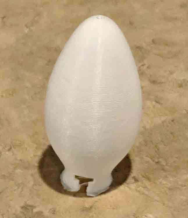
I was aiming for the classic look of an incandescent C9 bulb. I found a model of a C9 bulb on
Thingiverse.
I was able to modify a "T" shape into its base to make it clip right over the LEDs I selected.
Left is original model. Right is modified for clipping onto wire.
I 3D printed 50 of these covers. This was a lengthy process as each cover took about 40 minutes to print. After I fitted them on the LEDs, they exceeded my expectations in terms of evenly spreading the light without distorting the color.
Programmability was another main goal of this project. I wanted it to be easy for the user to change what the lights were displaying, and I wanted to give them the tools to be able to easily create a unique pattern and add it to a light show. The best solution that came to mind was an app that allowed the user to control their lights over their local wifi network.
I had never made an app before so this would be my playground to learn. I started with a basic single page app that allowed the user to select from a few hardcoded devices and set all of the LEDs to the same color based on four color sliders. The four sliders correspond to red, green, blue, and white. Each of the individual LEDs has 4 separate channels (red, green, blue, and warm white), so this gives the user a lot of flexibility in terms of color selection. Once the user has mixed the colors to their liking, they can select a device from the dropdown menu (Christmas lights is the current device) and press the "Send" button. The light driver tied to the "Christmas lights" name then displays the color based on the selection. This worked quite well, but it made my lights no better than the ones in a store so I had to go further.
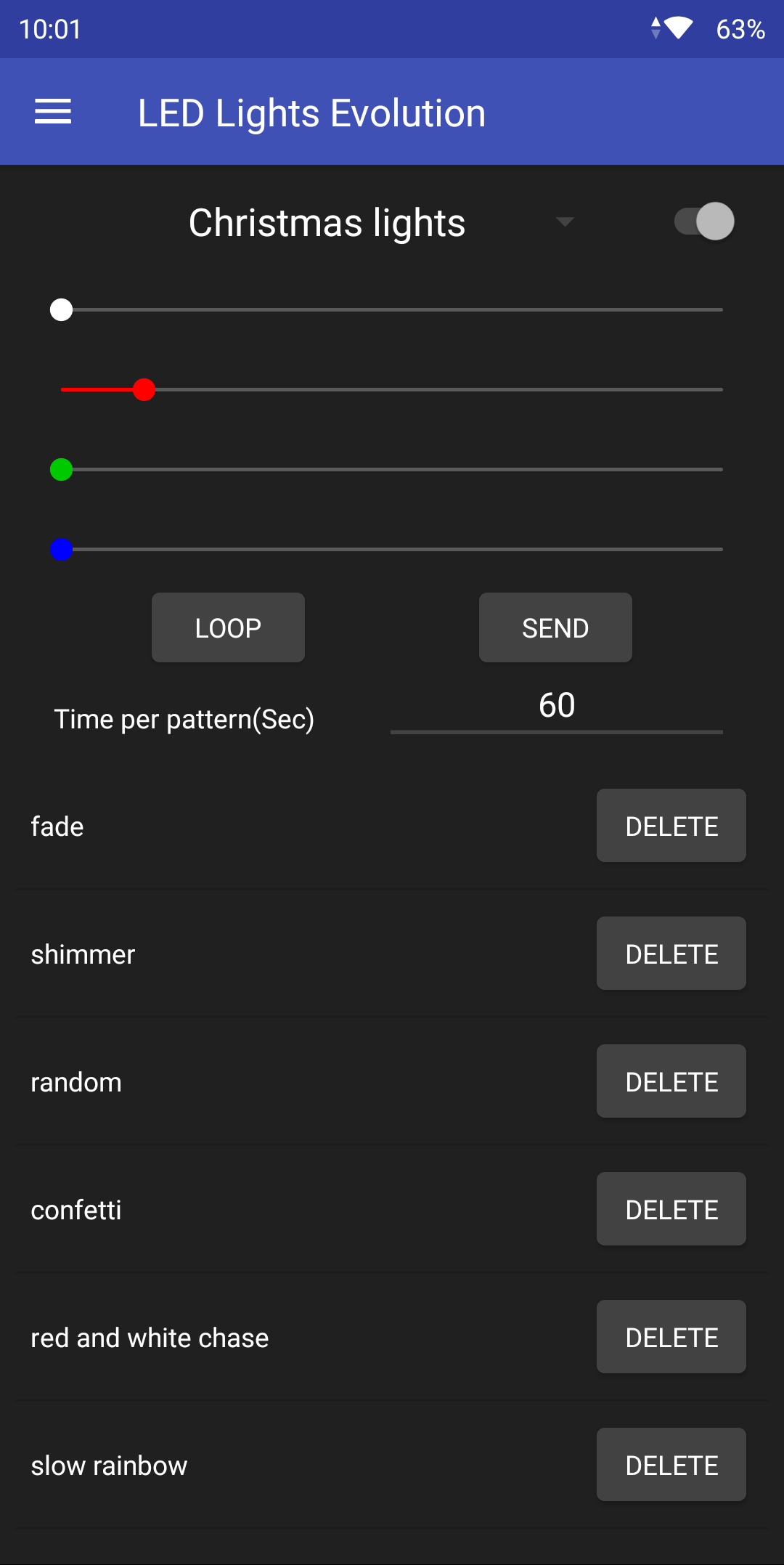
The bottom half of this screen on the app is dedicated to light shows and user created patterns. The user can look at the list of their patterns, select how long each pattern will display, and click "Loop" to start their light show.
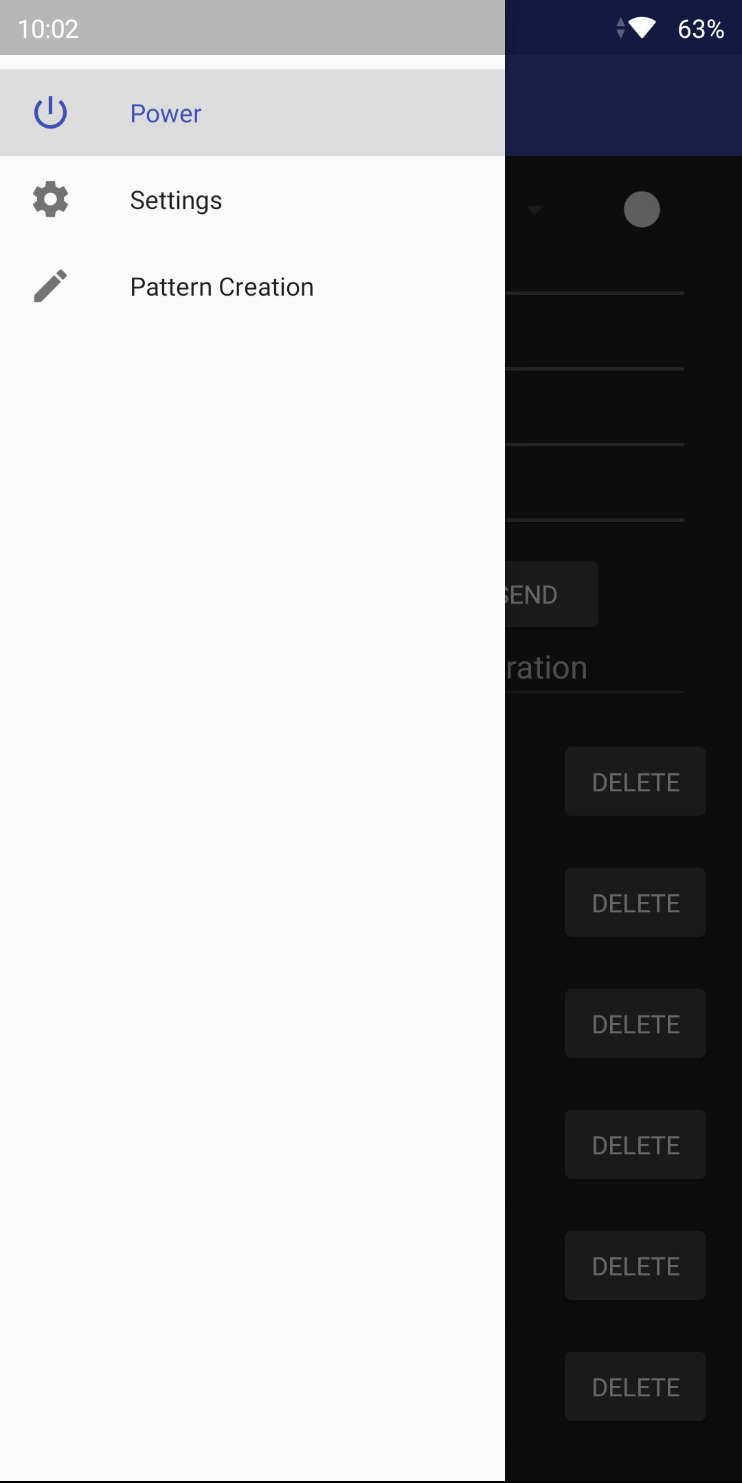
Like I mentioned before, I wanted the user to be able to create unique patterns so I designed a pattern editor. I added a navigation drawer to switch between functionality in the app.
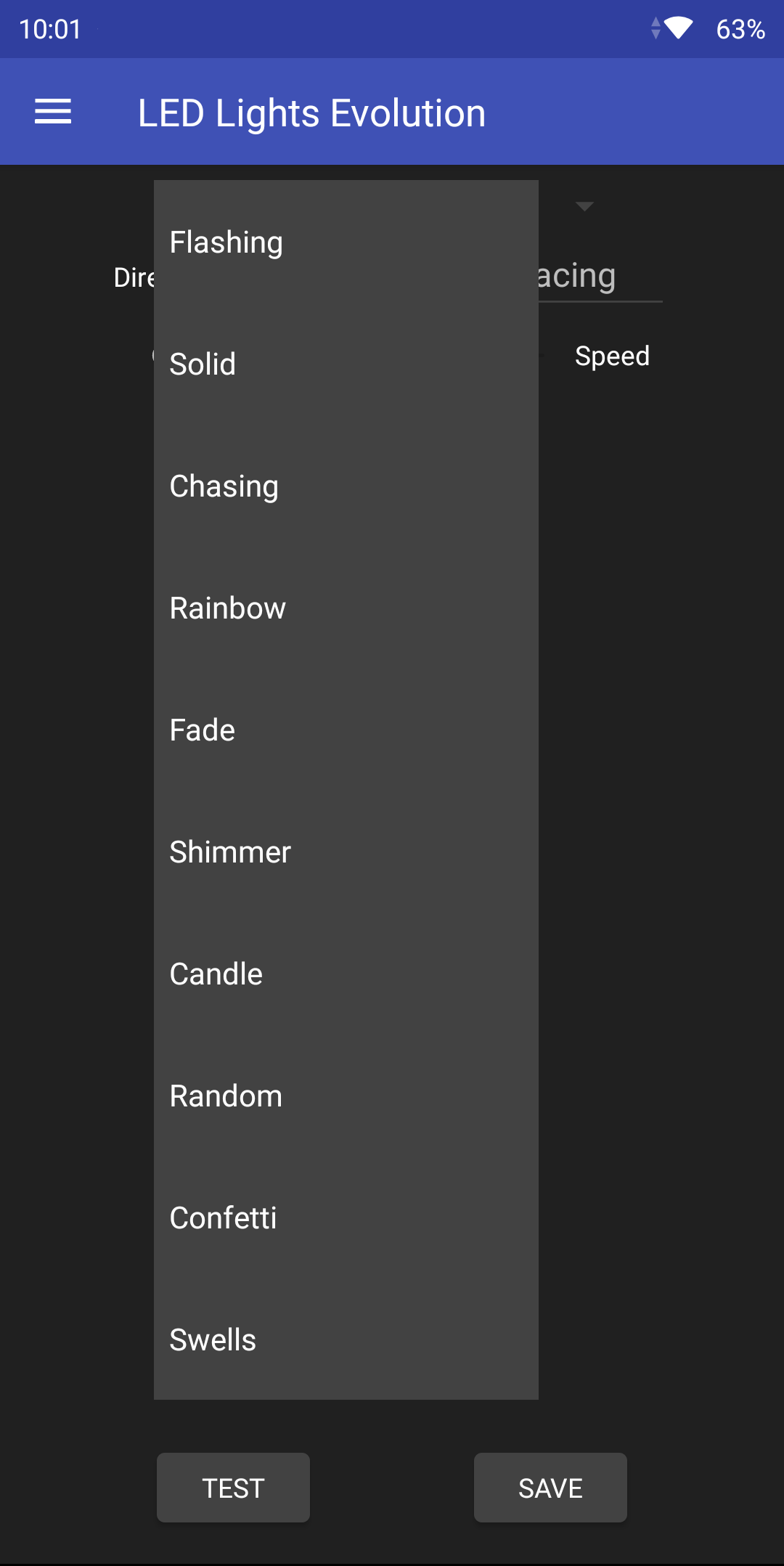
The Pattern Creation tab lets the user select from base animations and build on them. As shown in the dropdown menu, the provided base patterns are Flashing, Solid, Chasing, Rainbow, Fade, Shimmer, Candle, Random, Confetti, and Swells. Each pattern is tied to a fragment which holds configurable parameters.
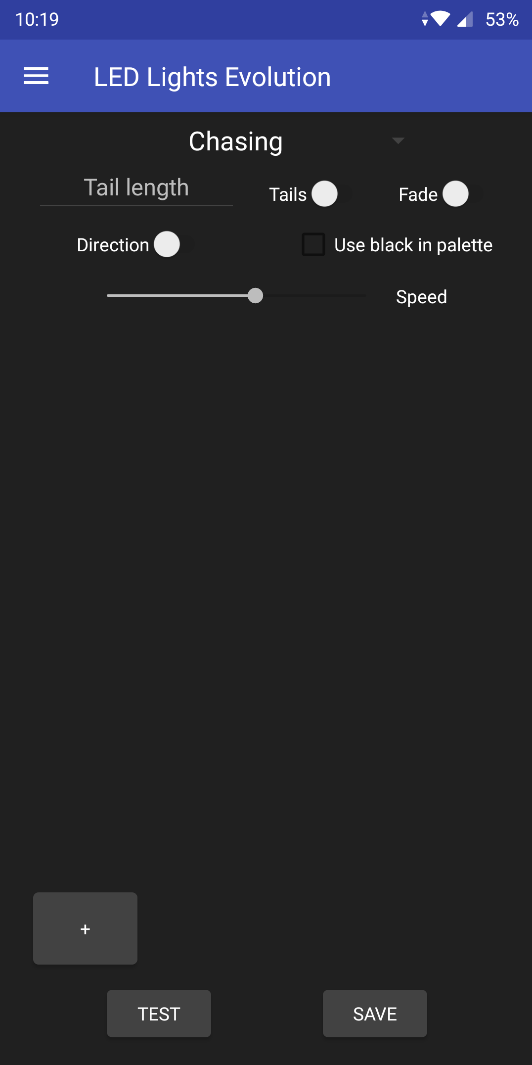
Take the chasing animation as an example. This gives the user a bunch of options to generate many different light patterns. Tails toggles whether or not the color fades out as it is going across the display. Fade controls if the color fades in. Tail length allows the user to select how many light bulbs the fade in/fade out takes place over. "Use black in palette" allows the user to select if the initial bulb is completely dark on the fade in/fade out. Speed and direction are self explanitory.
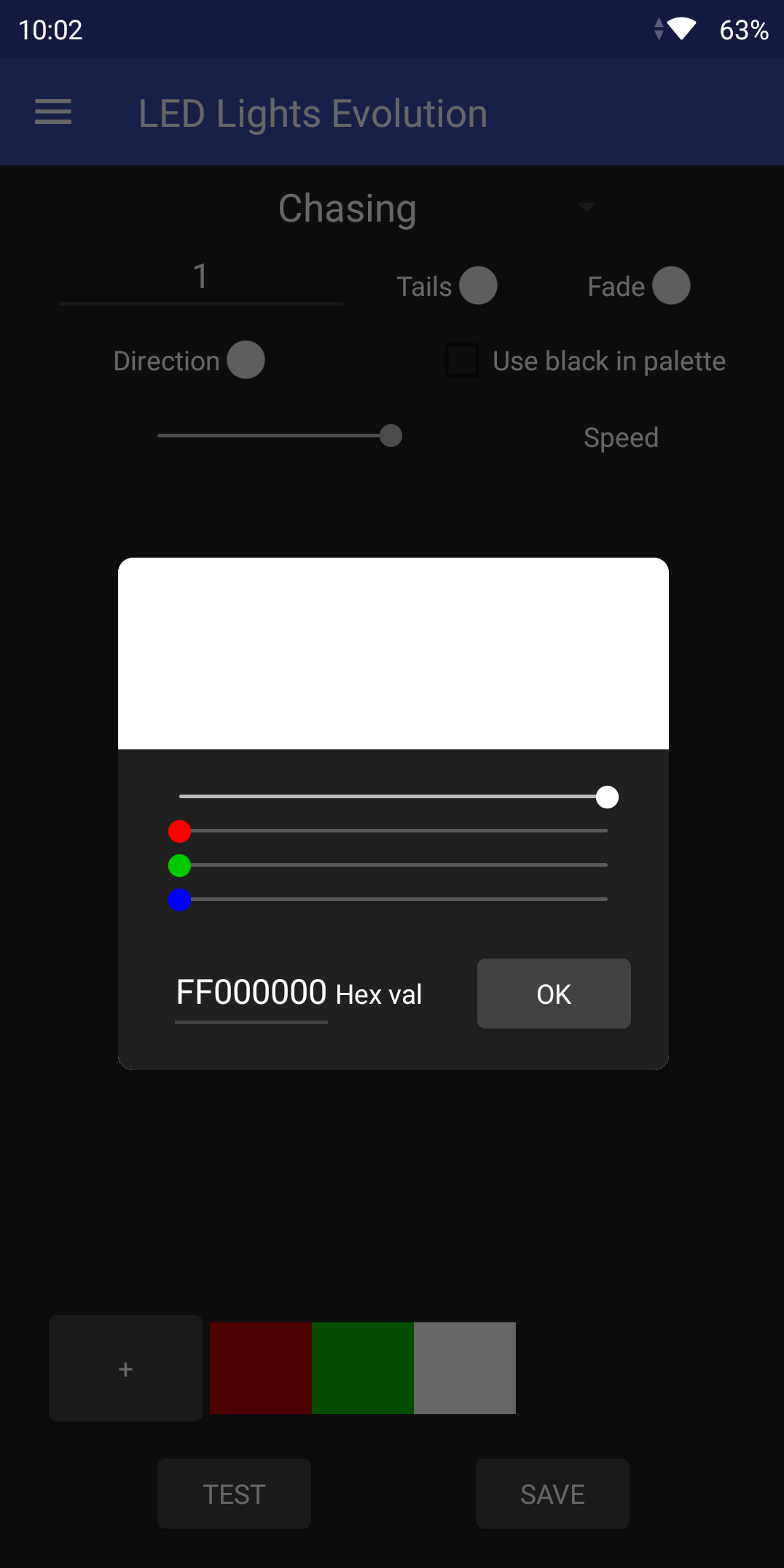
The plus in the bottom left corner allows the user to create a color pattern. They can choose a single color, or multiple colors. When they push the plus button, they get a small color picker which simulates what the color will look like. Once they hit "ok" the user can push "test" to send the pattern to the light display. They can edit the colors and parameters until the pattern matches their expectations, and then press "save" to give the pattern a name which will show up in the loop list.
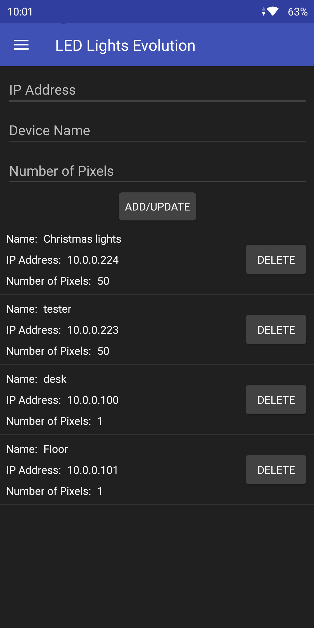
Since it is possible that the user will have multiple LED drivers in their house, I made it possible to add/delete devices to the device list.
There was also a lot of programming that went into the ESP8266 controller. It's a lot less pretty to show off, but I essentially made classes for each pattern with their parameters and created a basic API for the app to interact with. It can determine whether or not the light display is on/off, turn the whole display on/off, set a single pattern, or accept a whole set of patterns to loop over.
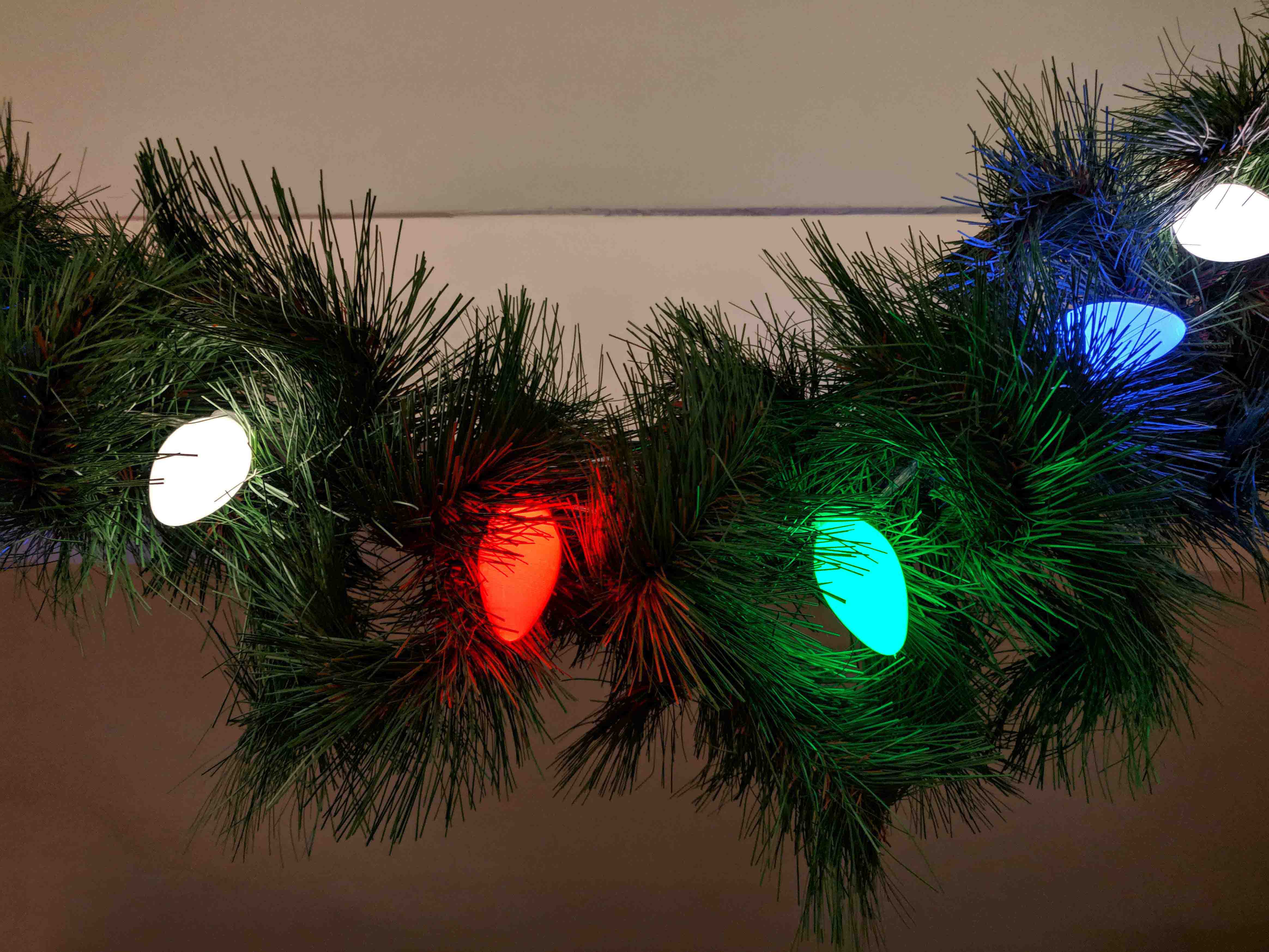
Here are some examples of what the lights look like in action:
Chasing - no tails - Red, green, white pattern
Chasing - with tails - Red, green, white pattern
Confetti pattern
Fade pattern - between white and red, green, blue, white
Red, green, white flashing pattern
Rainbow pattern
Random pattern
Shimmer pattern - emulates an incandescent flicker set
Swell pattern - a small section of lights brightens and sweeps across the display
Core A8 Conversion
A few years ago I got my first 3D printer. At that time, the trendy printer was a Anet A8 which was a flat pack kit that you built almost entirely yourself. The Anet A8 is an inexpensive clone of a Prusia i3 printer. The kit took about 15 hours to fully assemble due to my amateur understanding of 3D printing.
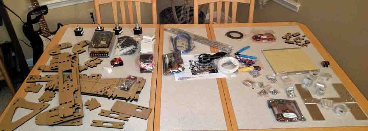
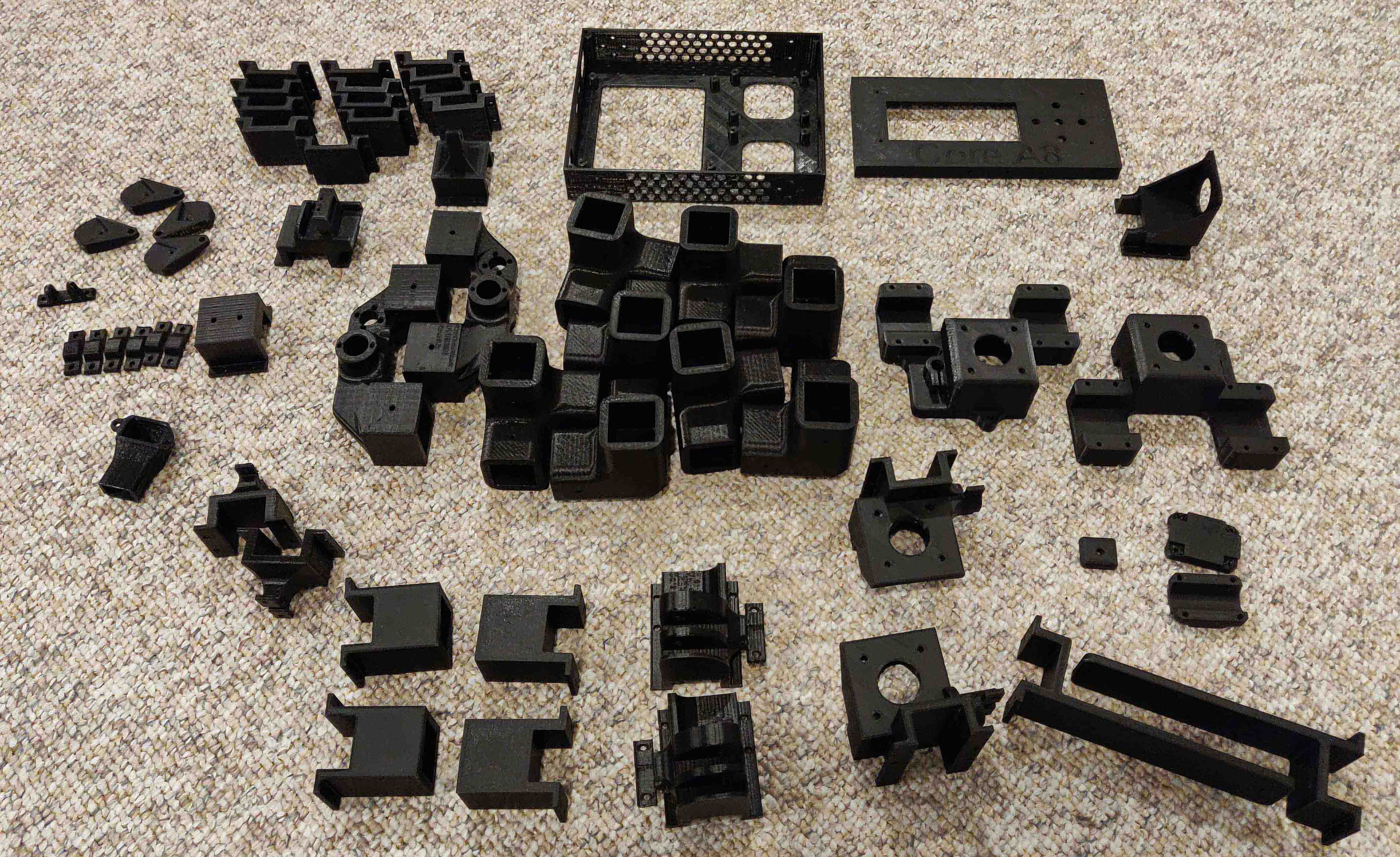
Anet A8 kit pieces.
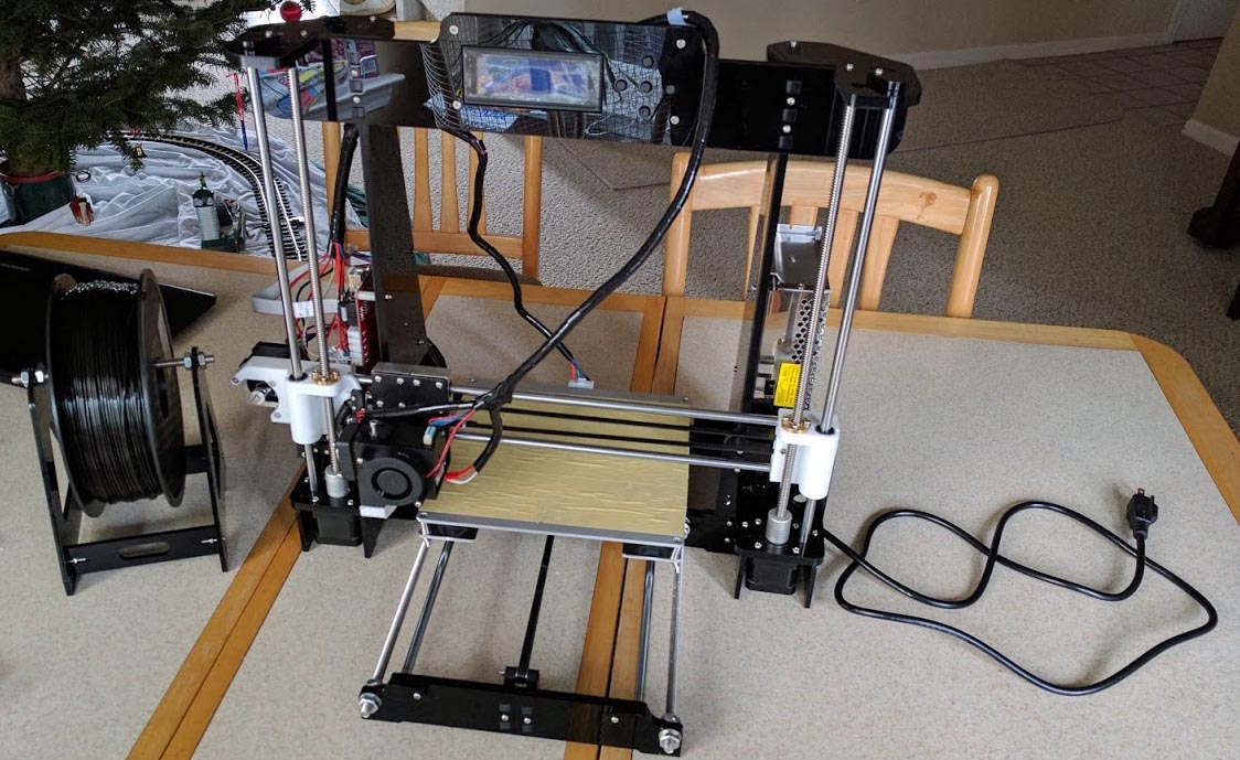
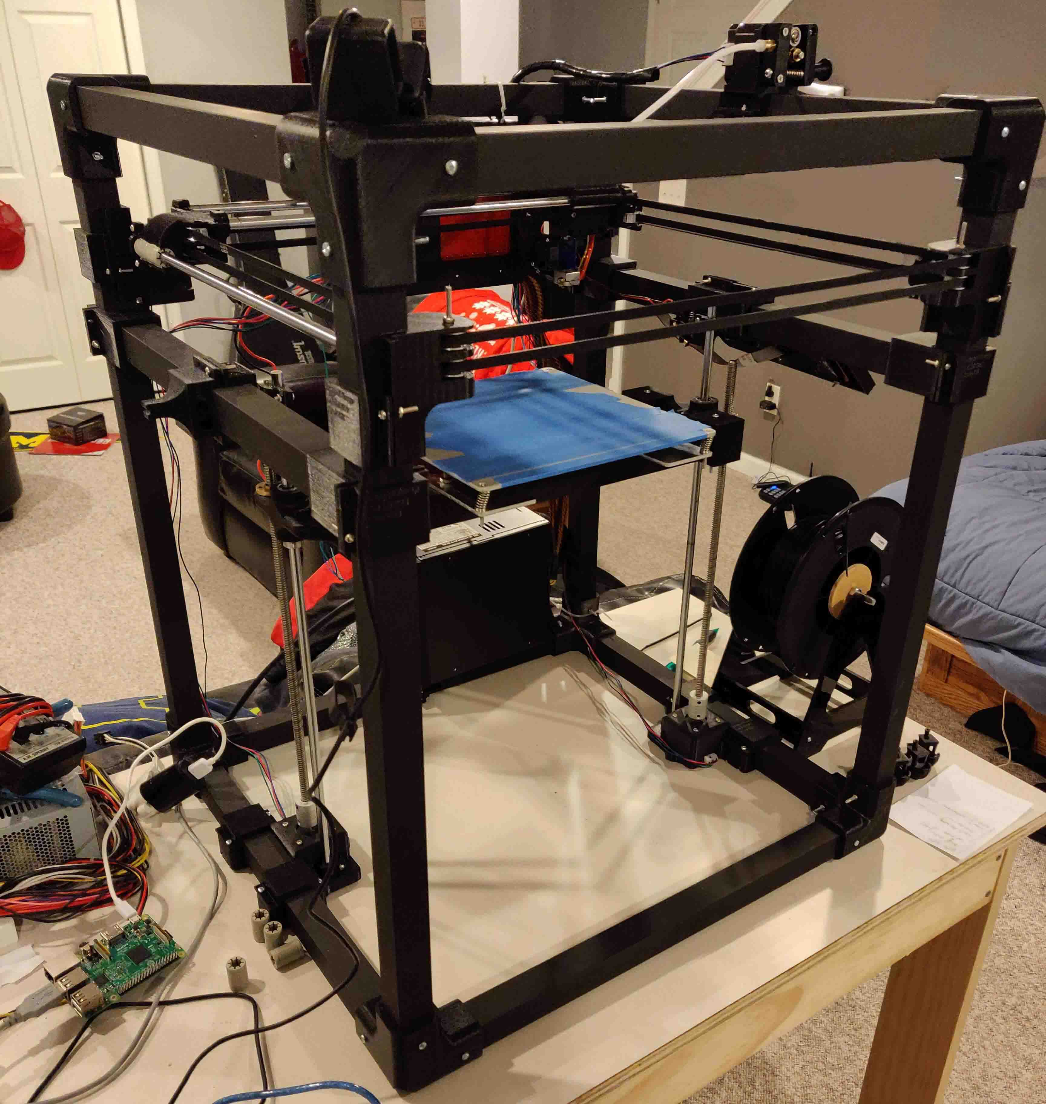
Fully assembled Anet A8.
The Anet A8 is capable of producting prints of fairly good quailty. They are amazingly good for the price. However, the low cost of the printer means that corners were cut. The acrylic frame does not make a good rigid foundation and tends to flex and wobble which lead to surface artifacts on prints. Additionally, cartesian printers that use a moving bed as part of their kinematic design tend to be slow and introduce more surface imperfections since the heavy mass of the bed cannot be accelerated quickly.
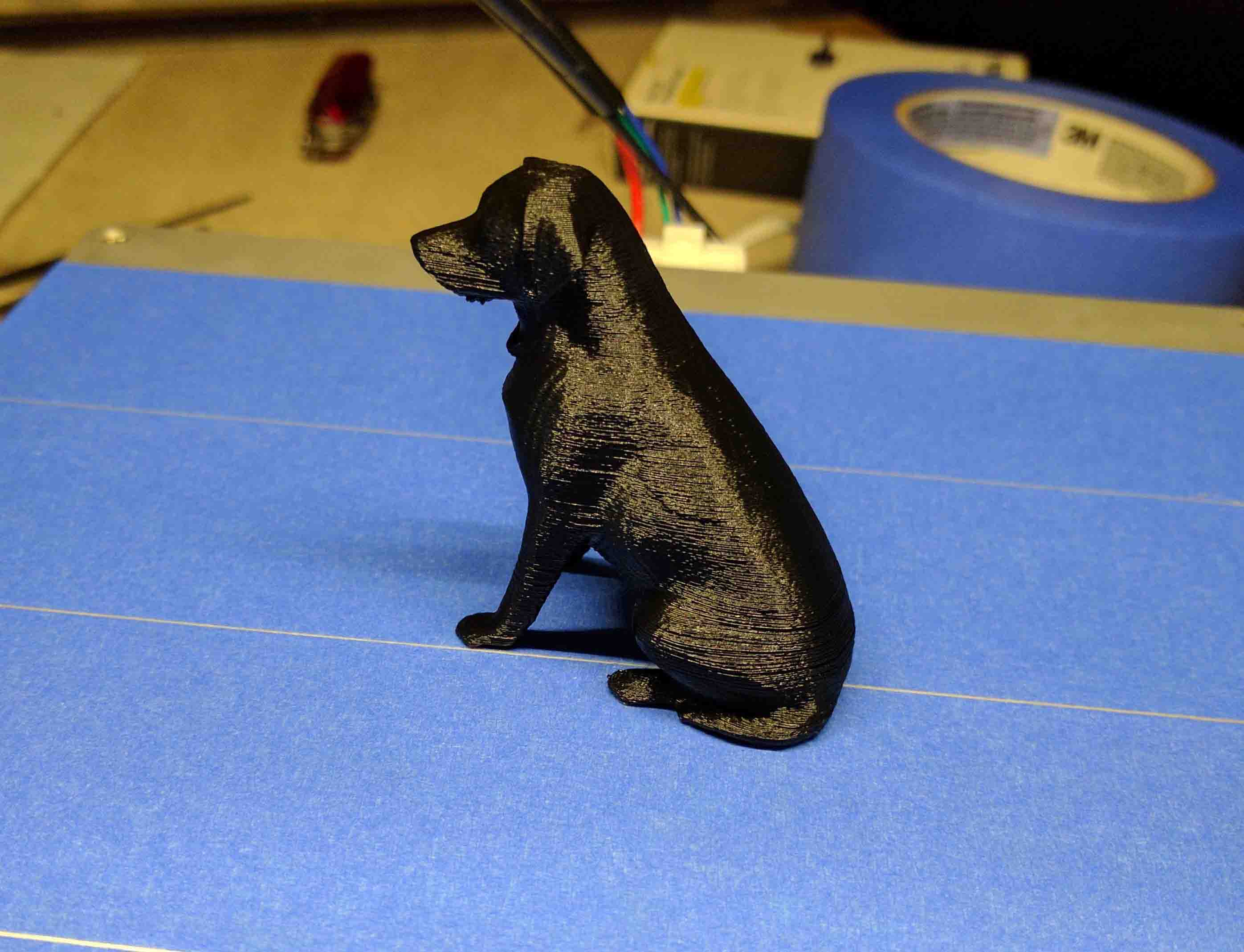
Small print of a lab. Its not a bad print but you can see the layers are not well alligned.
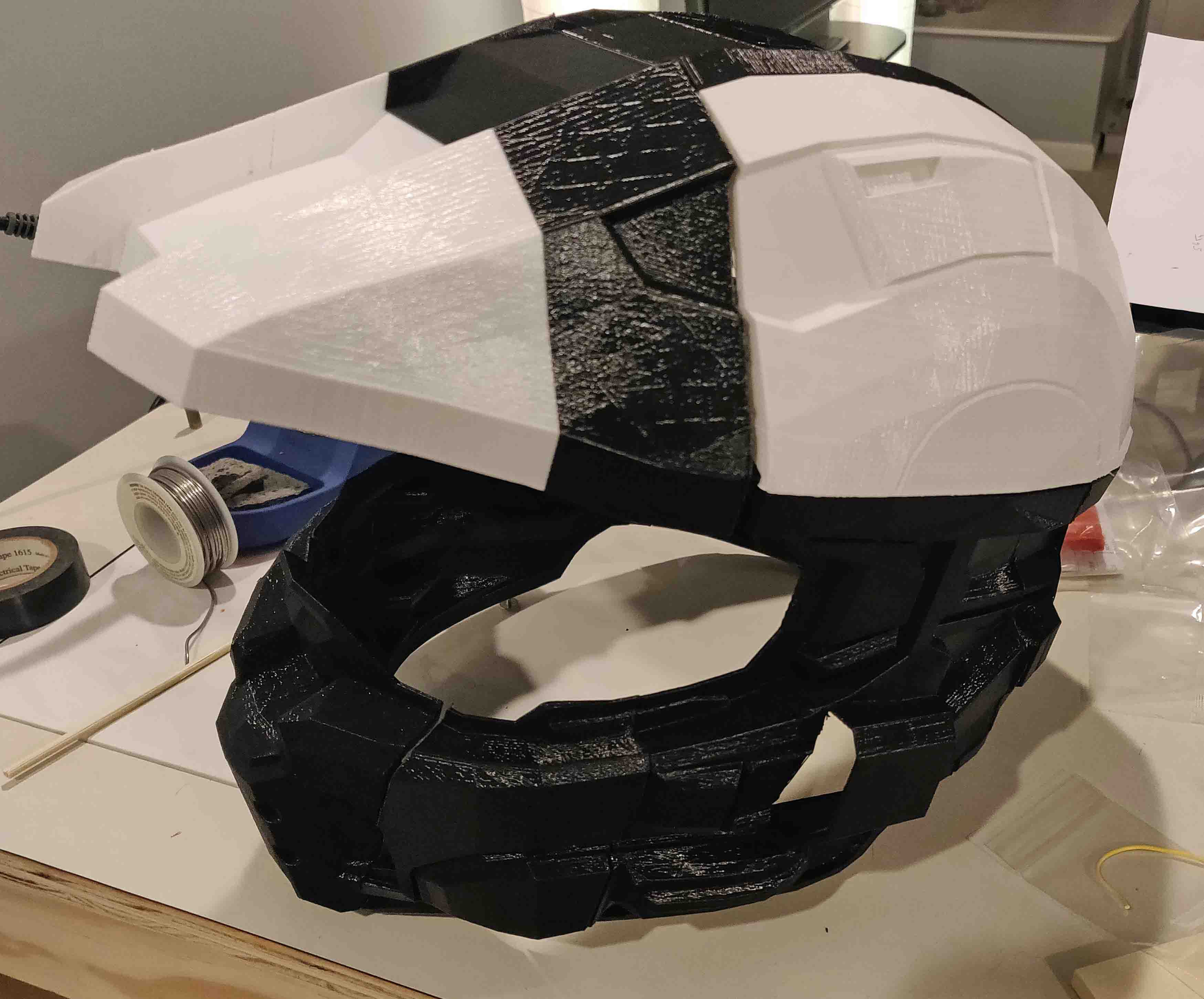
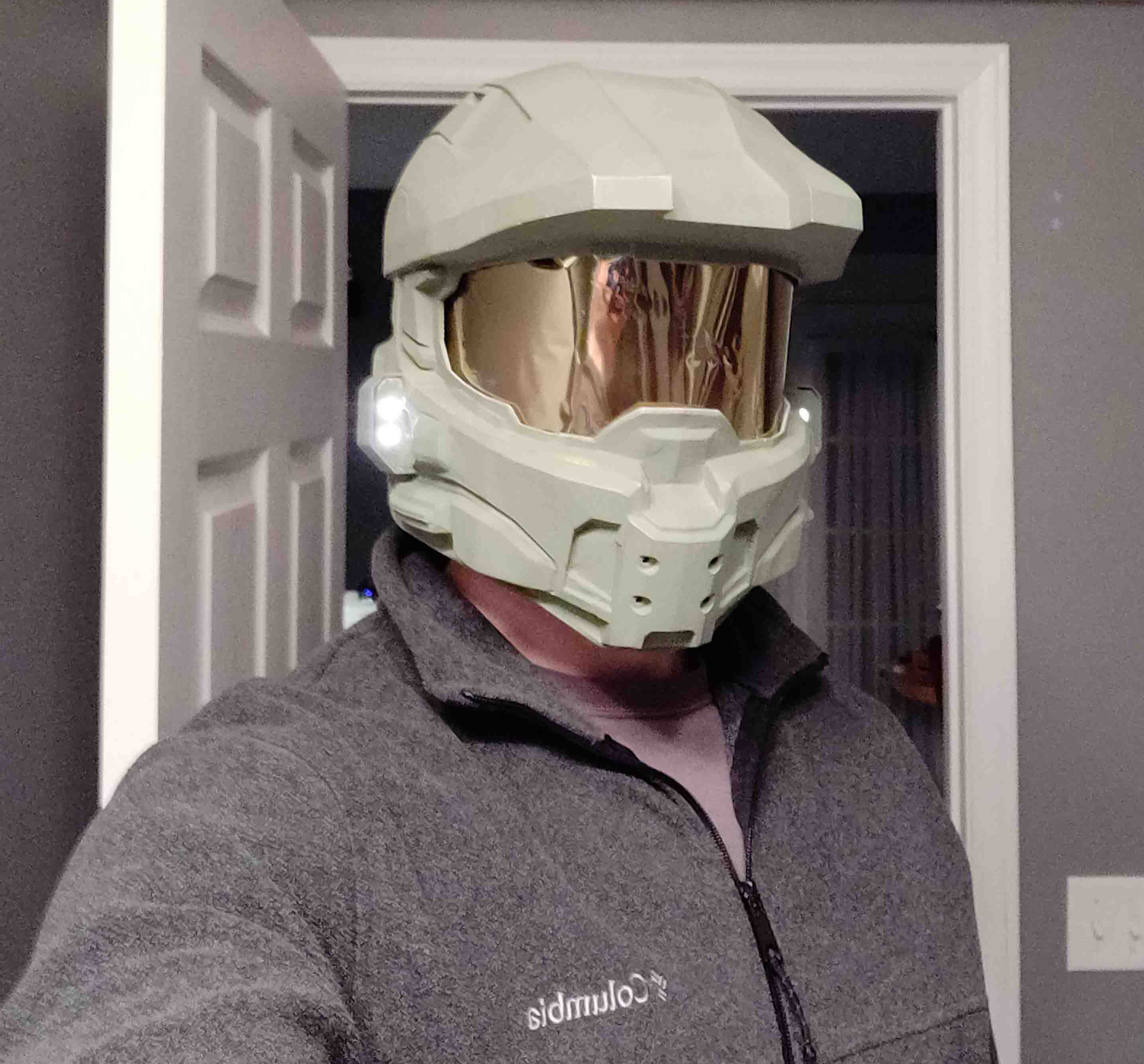
Another project printed on the Anet A8. Again, the printer is capable of really cool prints. Not only was this over 100 hours of printing, it was another 50+ hours of post process - sanding, gluing, and painting. Who doesn't want a life size Master Chief helmet though?
After assembling my Master Chief helmet, I decided to upgrade my printer so post process wouldn't be as neccessary. There are tons of options out there. Not only are there cartesian, but there are delta printers which use 3 arms to control the location of the extruder. Deltas are super fast but also introduce strange artifacts in the surface of prints. I then found the Core XY design which I thought suited what I was looking for most. The Core XY desgin allows the moving mass to be minimized, and allows for a large build volume.
Thankfully, since the Anet A8 is such a popular printer, many people have done crazy things to them! I found designs that incorporated most of my Anet A8's parts and produced a Core XY printer. Even more interesting, a vast majority of the new printers parts are 3D printed.
I went out and bought all that was necessary to follow the build. 24 feet of 1" aluminum tubing, a bowden extruder, 3KG of filament, and extra M3 nuts and bolts. After about 150-200 hours of printing on my trusty Anet A8, I had successfully printed its replacement.
I painted all of the aluminum tubing matte black to give the printer a clean black on black theme. Assembly took another 20 hours or so, and then I was able to print my first test prints to see if my hard work had paid off. I printed a model on my original Anet A8 and my new Core XY printer to compare quality.
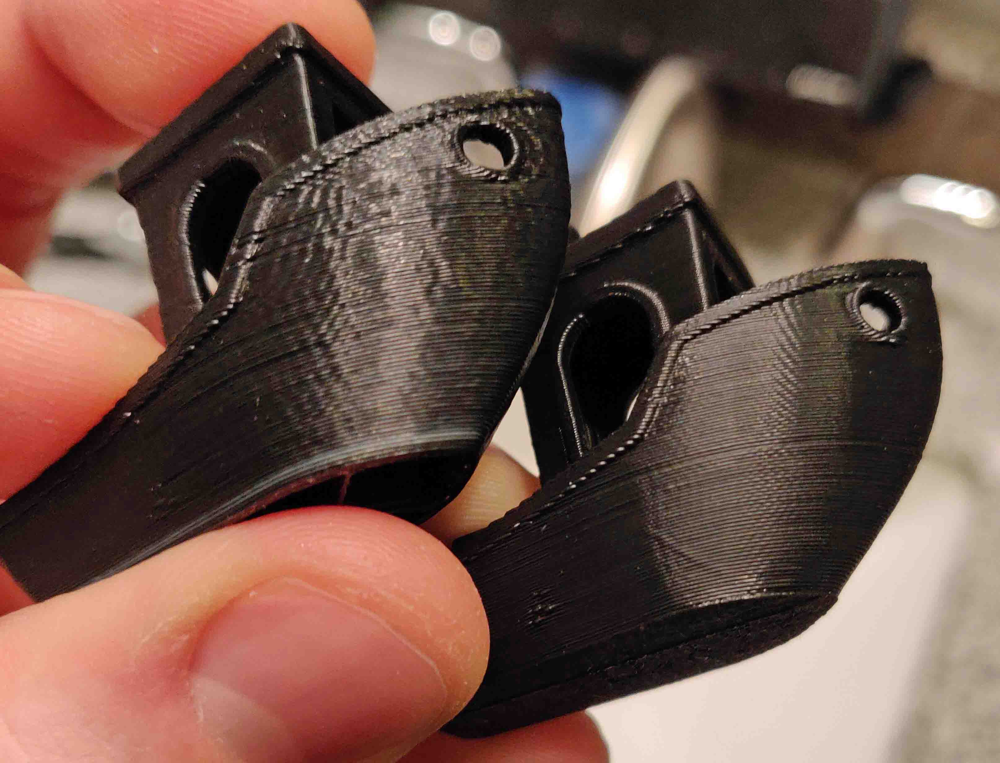
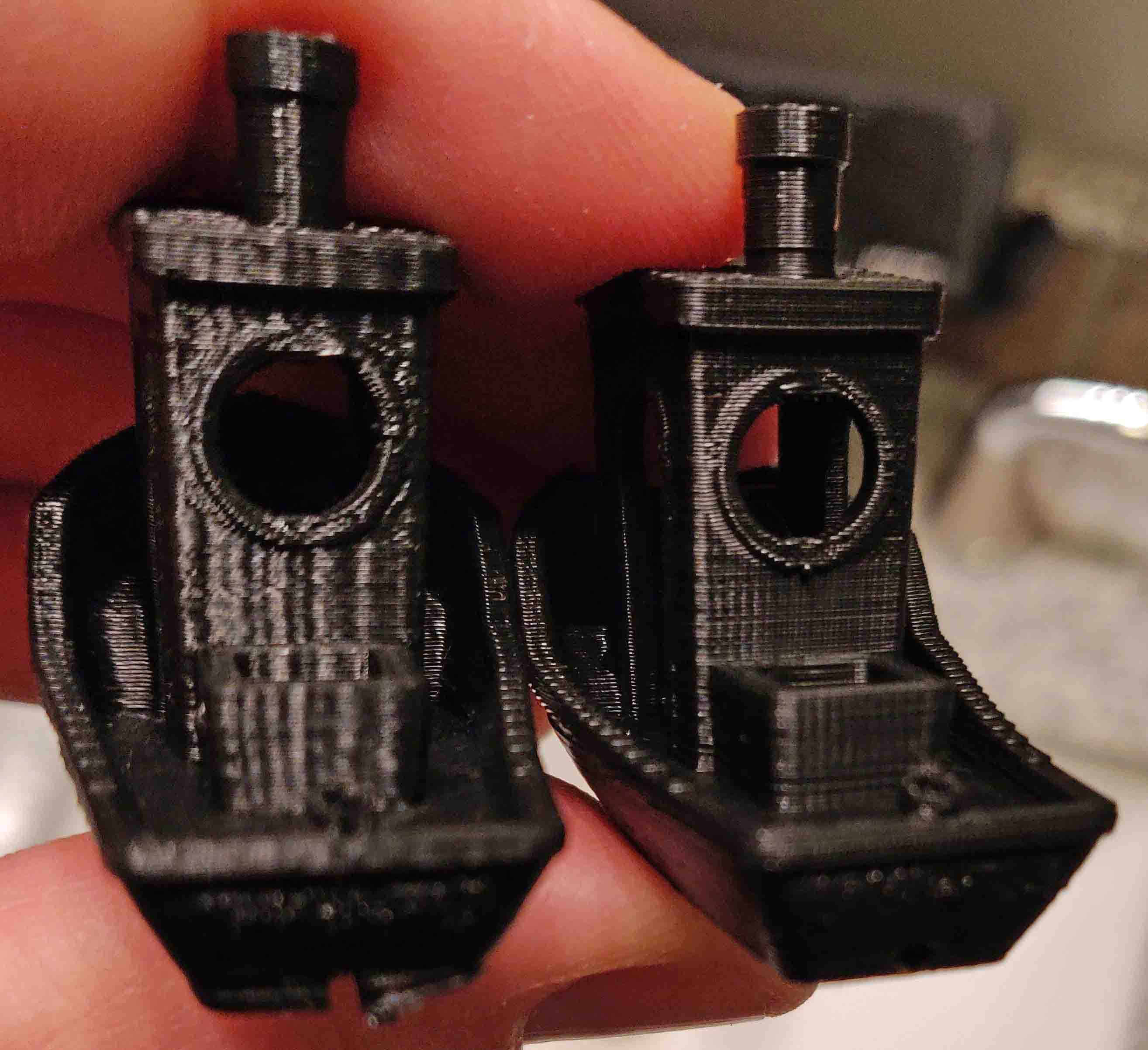
In both pictures, the left boat is from the original Anet A8, the right boat is from the new Core XY printer.
I was quite satisfied with the improvement in quality over the Anet A8. If you look at the surface finish the Core XY show less ringing/waves, which was the goal! Since the Core XY's frame is so much more rigid, I was also able to crank the acceleration settings up so the prints finish faster. The Core XY also offers a build volume of 310mm³ where the Anet A8 only offered 220x220x240mm.
At least, at the time I was quite satisfied. As I got more familiar with the printer, I noticed more of the design errors made. I ended up completely tearing this printer apart and building the same designer's revision called the Core A8 Slim. As you see based on my other 3D printer project, even this didn't yield the results I was hoping for. The plastic frame was impossible to square and wobbled forcing me to either print slow or sacrifice quality.
16x16 RGB LED Matrix
The idea for this project started with an 8x8 LED matrix. I wanted to make something visually interesting that I could hang on the wall. I also wanted it to be useful rather than just something pretty to look at. My goal for this display was to make a sign that would show the current temperature and the hourly weather forecast along with animated images to correspond with the forecast.
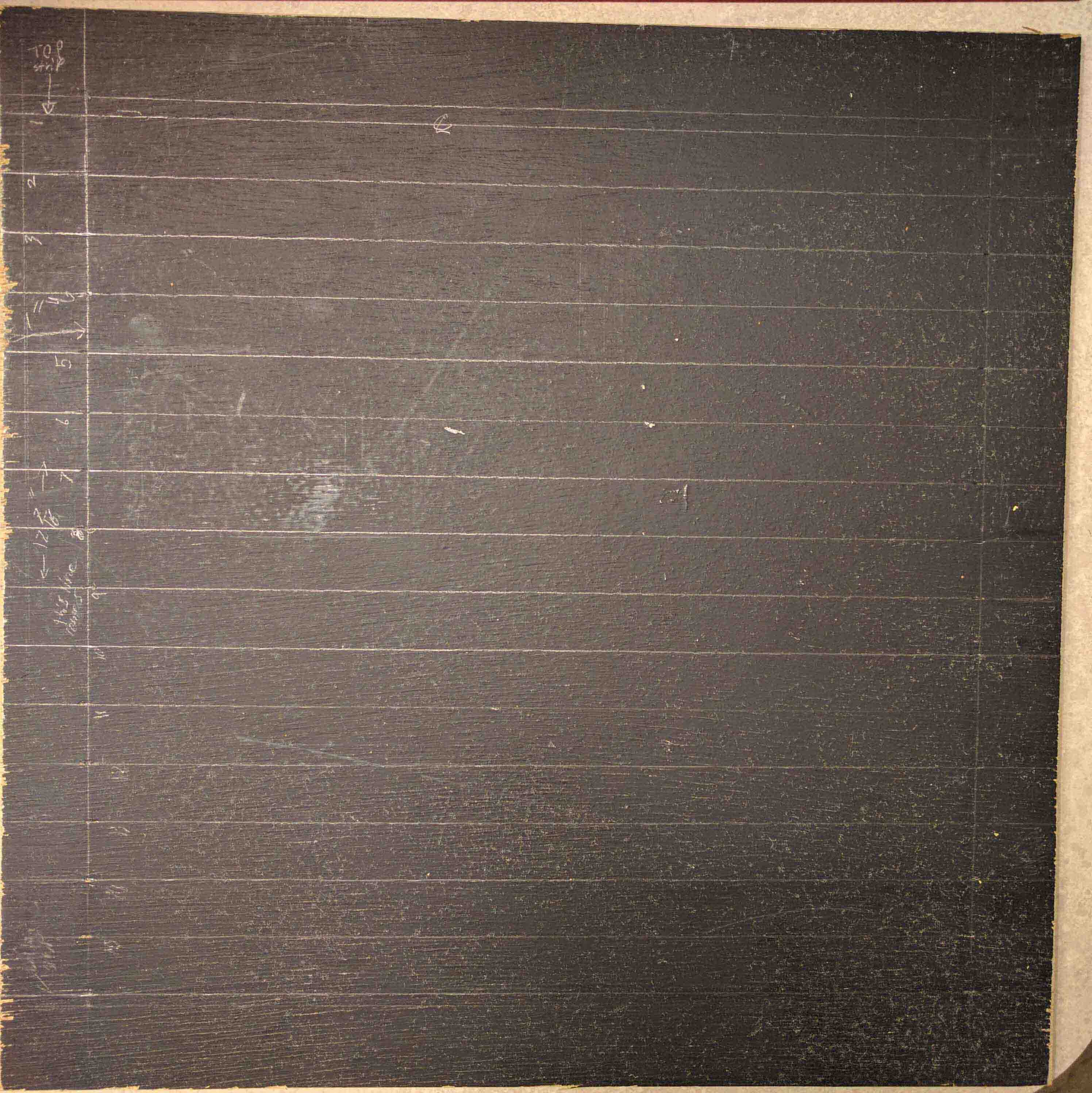
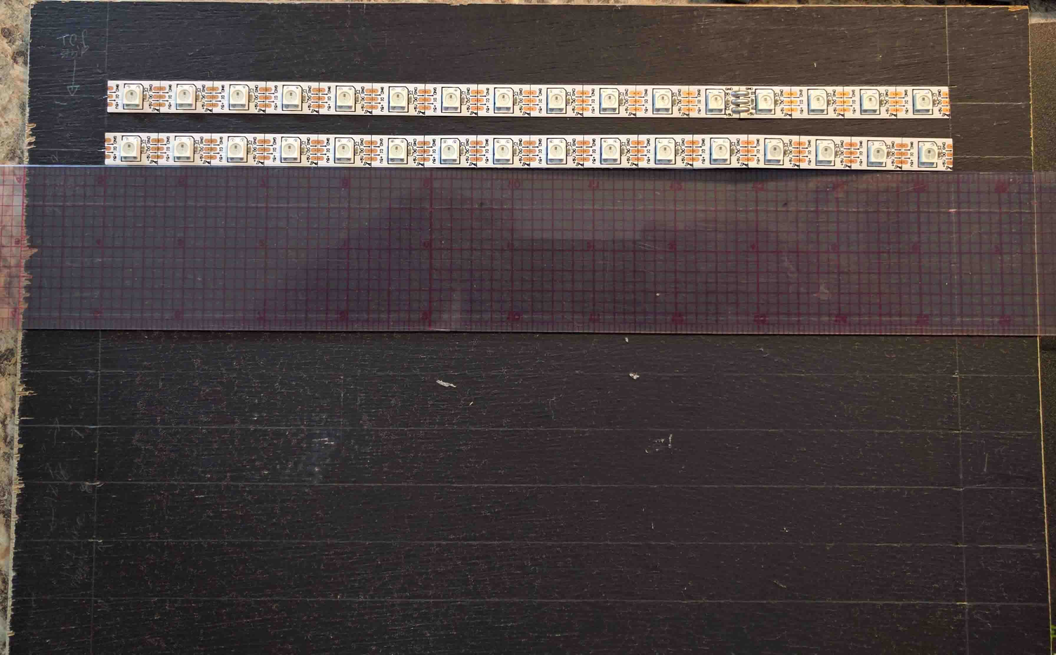
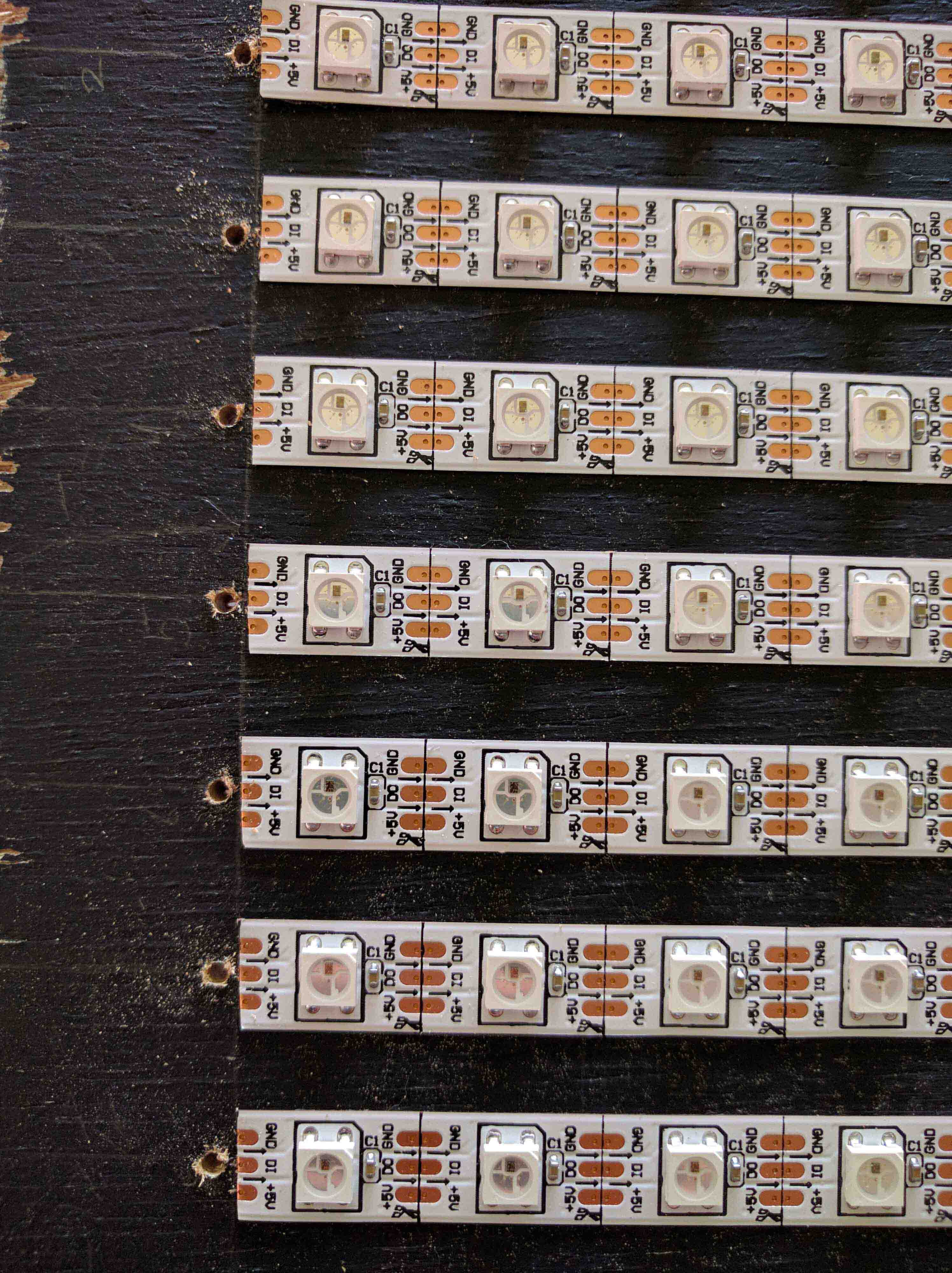
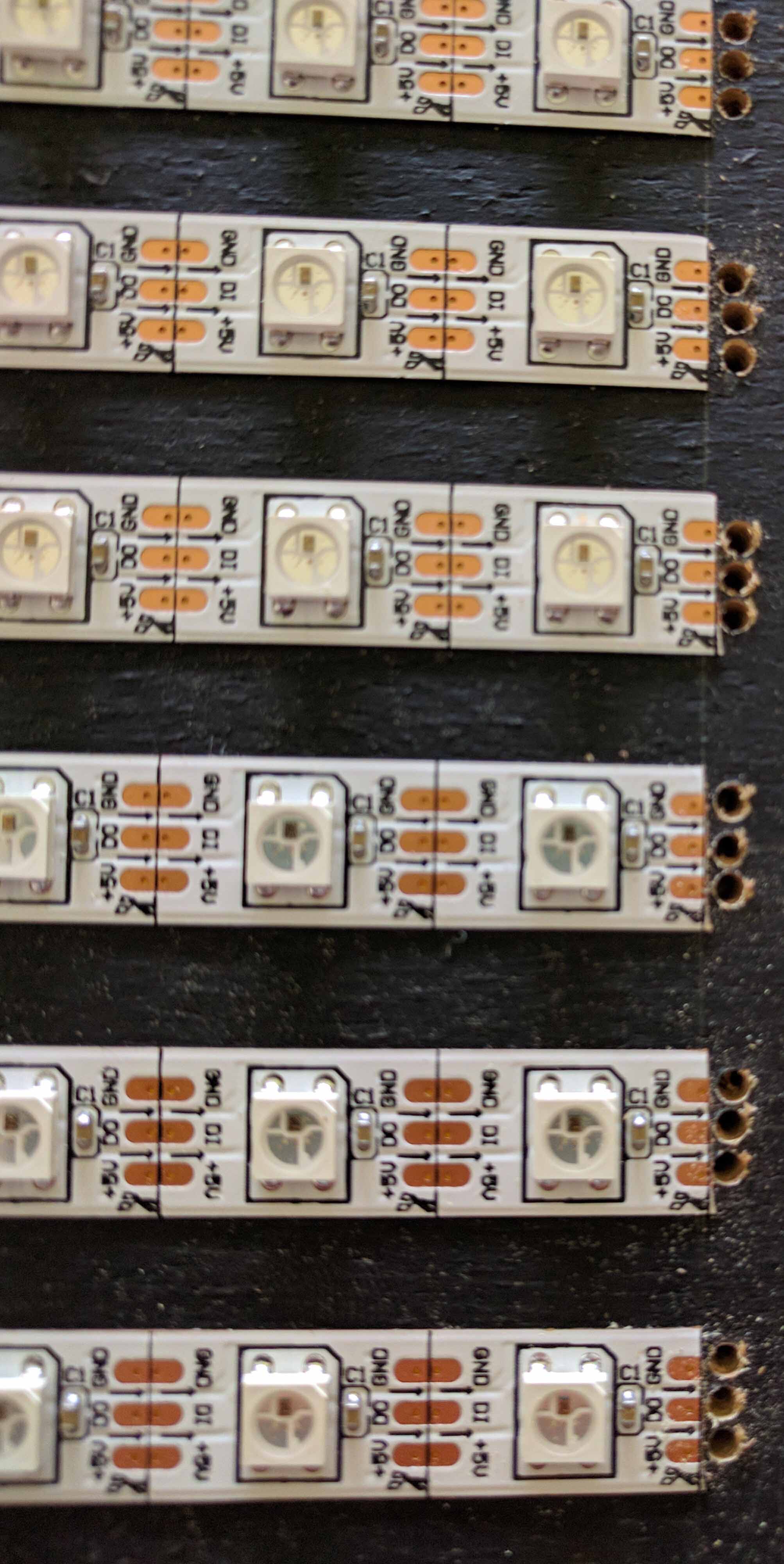
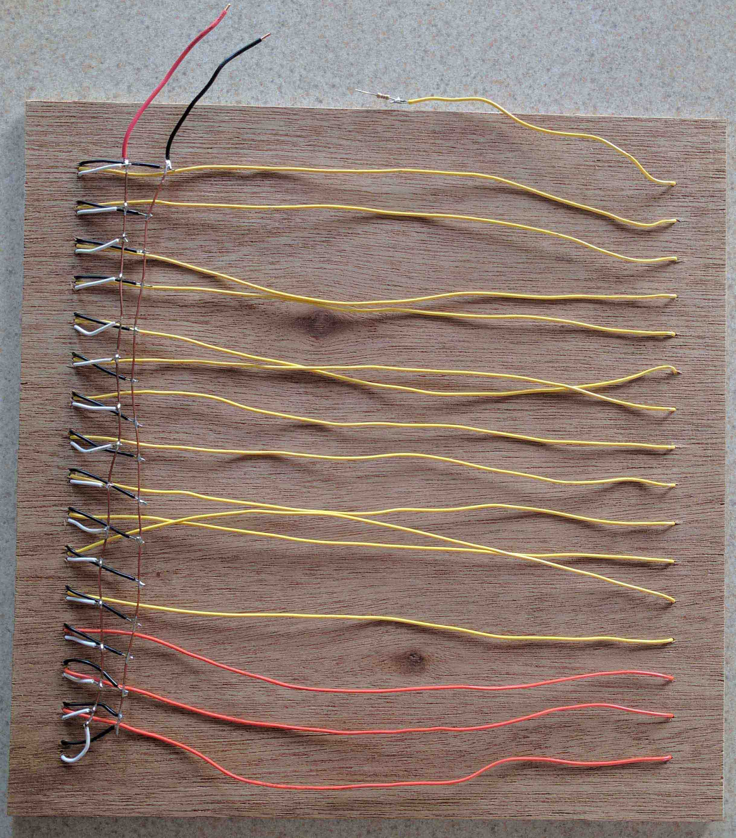
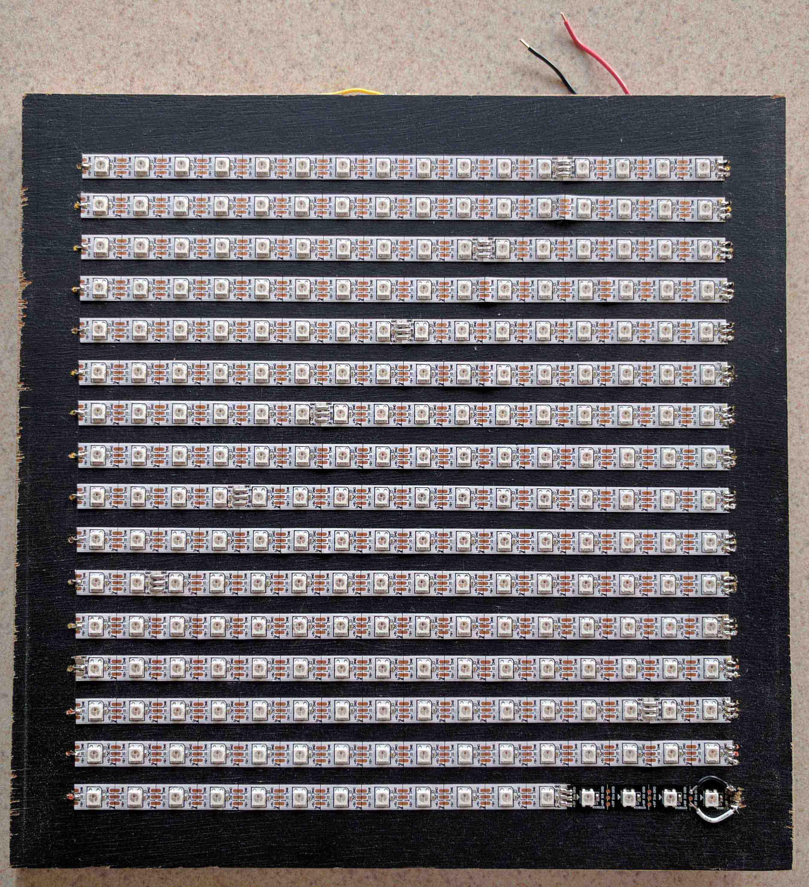
I started with a 12"x12" piece of luan and drew 16 equally spaced horizontal straight lines. I then cut and placed 16 strips of WS2812 individually addressable RGB LEDs (with 16 LEDs per strip) on these centerlines to form a LED grid. Next, I drilled holes to line up with the power and data pads on the strips and soldered all of the ground, 5 volt, and data lines together.
After soldering everything together, I started on the software side of things. I wrote a python script that allowed me to convert an image or animated gif into a block of comma separated values that makes up each frame of an image. I wrote the LED driver program in C++. The program periodically pulls data from the Weather Undrground weather api and displays the condition and outside temperature on the LEDs. To keep things interesting, the display also shows some "screen savers" between weather data updates.
Naturally, one of the first things I wanted to try to display was a University of Michigan block M logo. I found a 16x16 block M on the internet, ran it through my script, and tried it out on my matrix.

Original image.
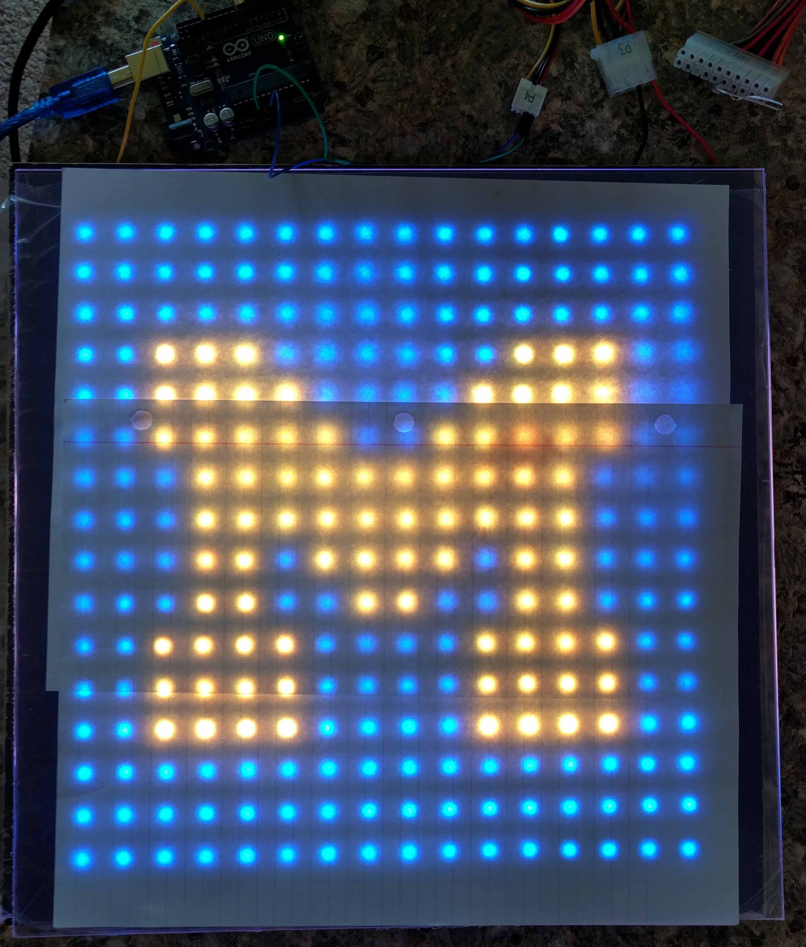
Image after conversion being displayed on board.
Now that image conversion was a relatively painless process, I set out to find animated gifs that looked good on the matrix, and depicted certain weather conditions that corresponded to the Weather API that I pulled from. I found, created, and modified images until I was happy with how they displayed on the matrix. I created animations for the following weather conditions: flurries, rain, sleet, snow, thunderstorms, clear (sunny), cloudy, foggy, partly cloudy, and overcast.
After creating animations for display, I wanted to make a frame to hold the matrix. One of the side effects of these LEDs is that they are super bright if left uncovered. There needed to be a diffuser over them to help spread the light out. The diffuser helps reduce bright spots and blurs the image a bit. I chose to use plexiglass as the diffuser. However, plexiglass isn't opaque enough on it's own to diffuse the light. After trying to sand it with an aggressive sandpaper, I didn't get the diffused look I wanted. Next, I tried using a glass frosting paint. While the paint did start to provide a diffused look, after more than 15 coats the look still was not satisfactory. I finally used a coat of flat white spray paint. That finally achieved the look I was shooting for.
My dad is a good craftsman and he helped me make a nice frame to hold the diffuser and matrix. The matrix and diffuser had to be a specific distance apart from eachother to provide a good image to the viewer. I also had him cut ventilation slits into the top and bottom of the frame to allow air to pass over the LEDs since they produce a fair amount of heat during operation.
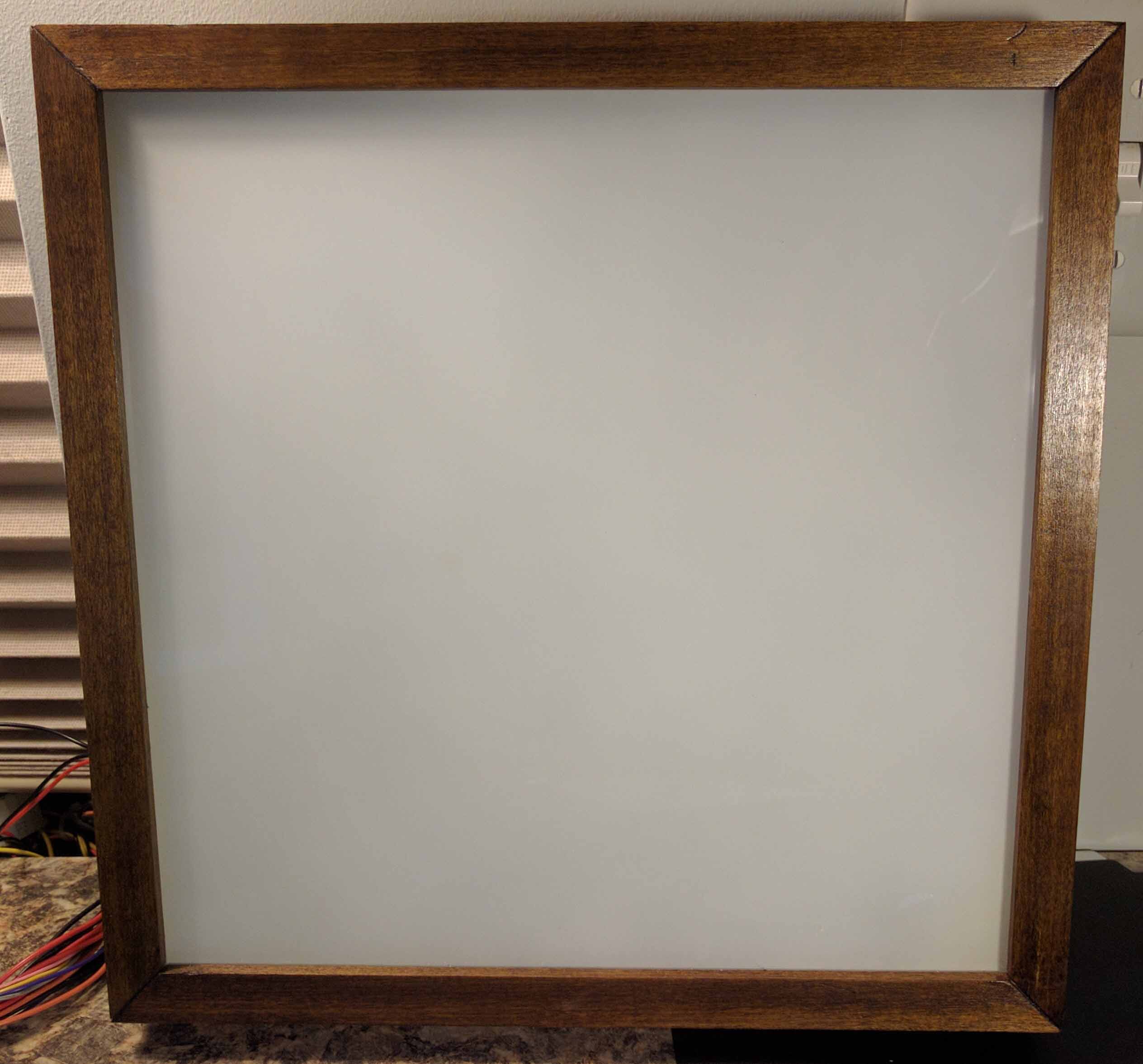
Framed matrix with diffuser in place.
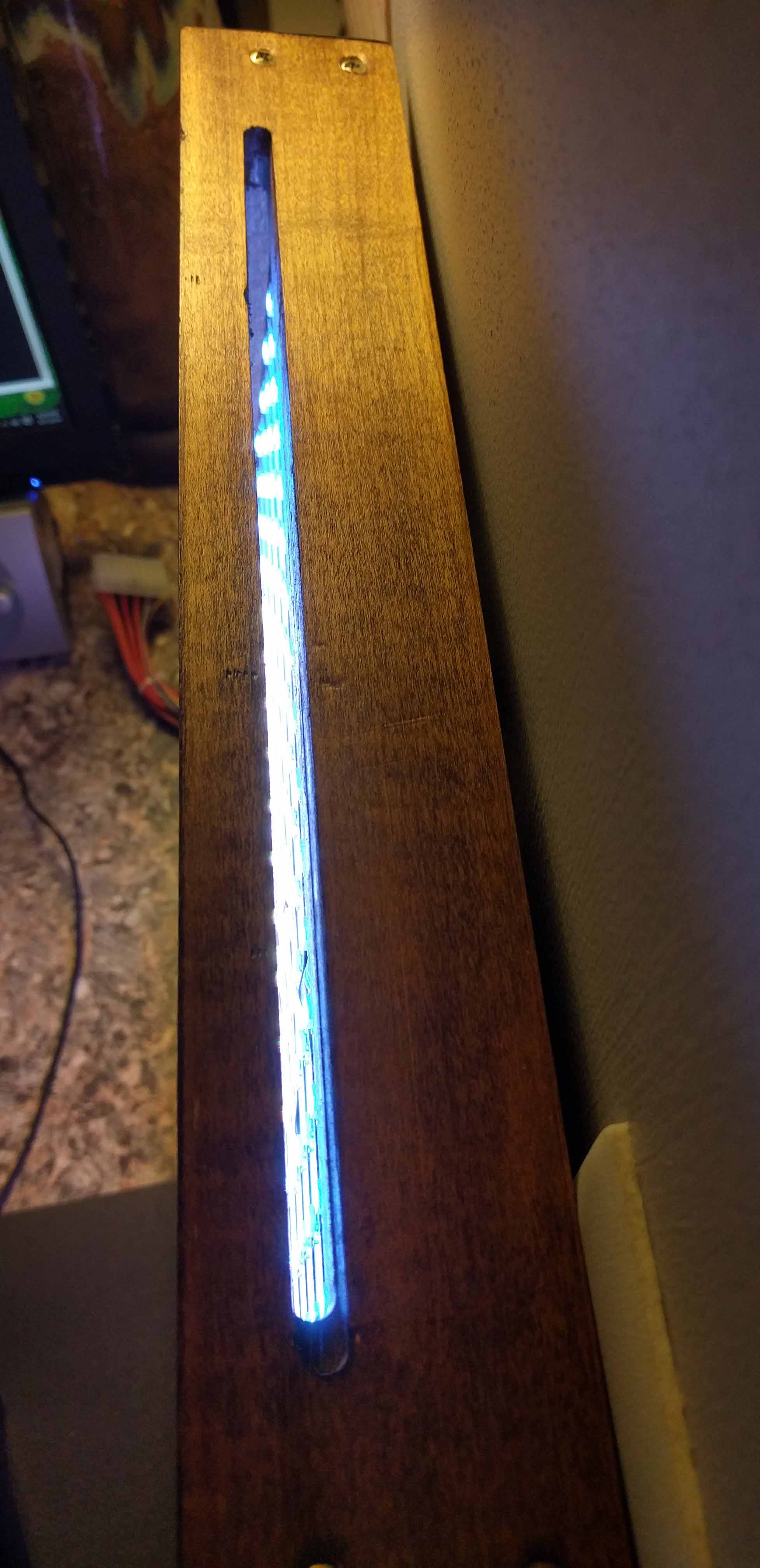
A view of the top air slot.
The matrix displaying the current weather: 77 degrees and Partly Cloudy.
LED Towers
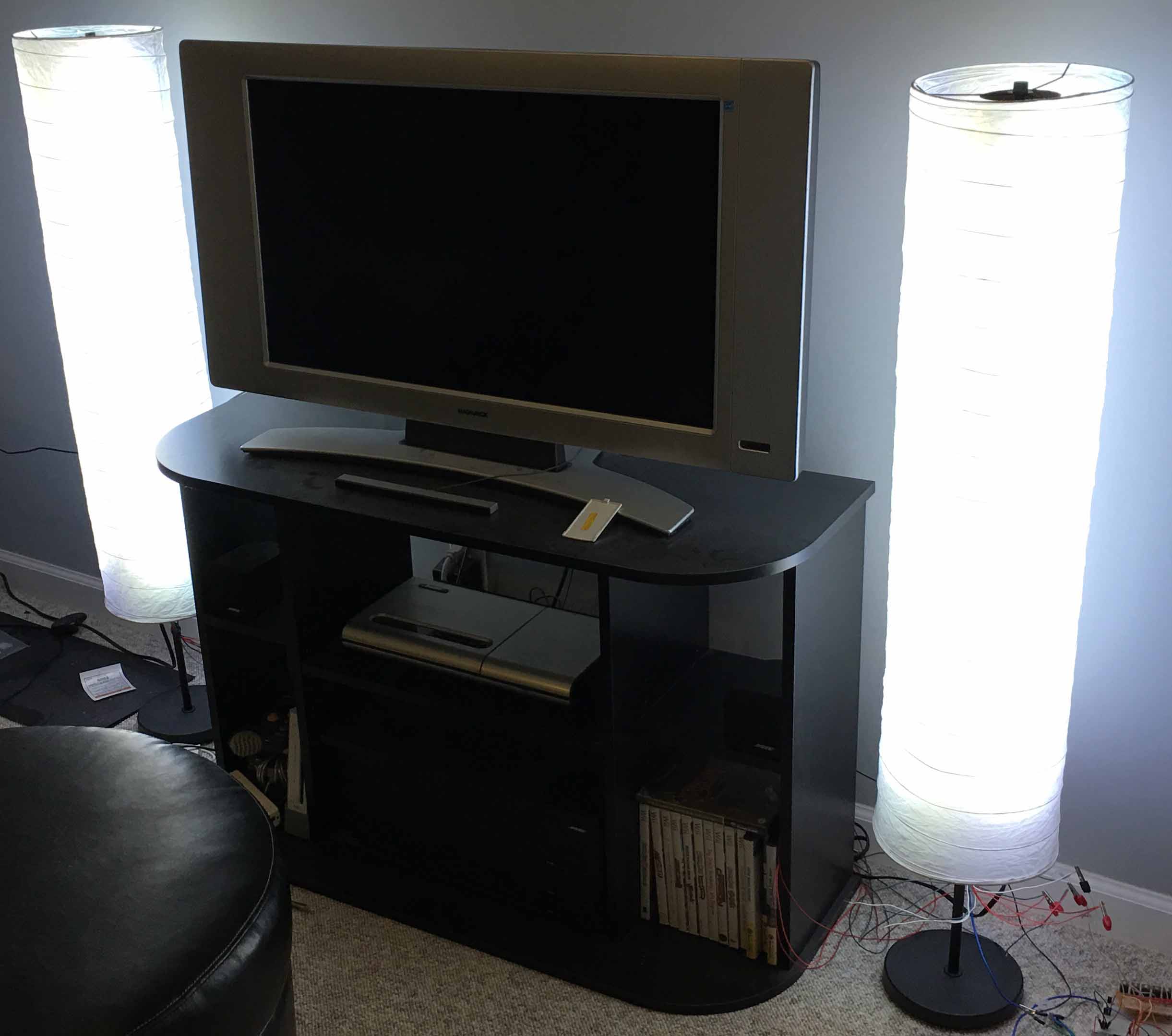
Being that my room is in the basement, I'm always looking for new ways to brighten things up. I purchased two floor lamps from Ikea and set them up next to my TV. For some reason, they only had one lightbulb each, and the light was unevenly spread -- biased towards the middle. I wanted to make them look better and put my own touch on them. So the experimentation began...
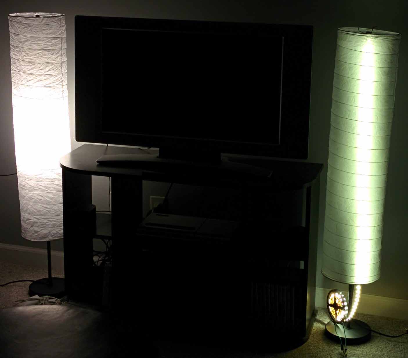
An original lamp is shown on the left. The lamp on the right has a single strip of 5050 Warm White LEDs draped inside.
It's easy to see that the color temperature of the LED strip is not very pleasing. They're a funny green/yellow color in comparison to the lonely single CFL in the original lamp. My solution to this was to add a 5050 RGB LED strip along side of the warm white strip to allow for custom color temperature adjustment.
Of course, LEDs are very directional. These LED strips only put out light at a 120 degree angle. If I only used one LED strip, the front part of my lamp would be lit, but everything else would be dark. At first I was going to attempt to position 3 sets of LEDs onto a large PVC pipe. PVC is fairly hard to cut and isn't very forgiving. I settled on using 3" diameter cardbaord packaging tubes.
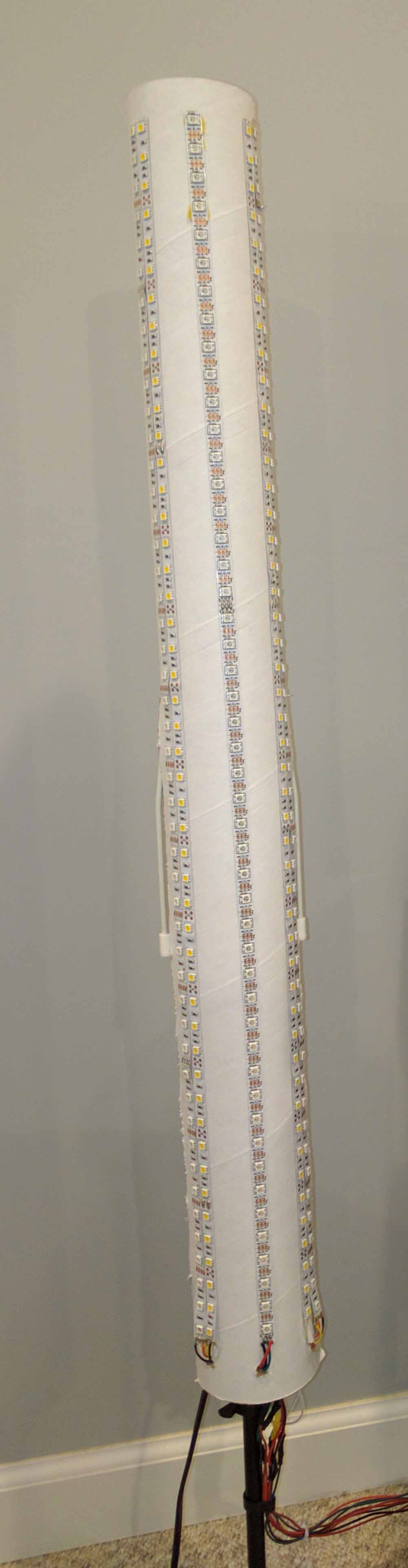
Left: One of the cardboard tubes with led strips attached.
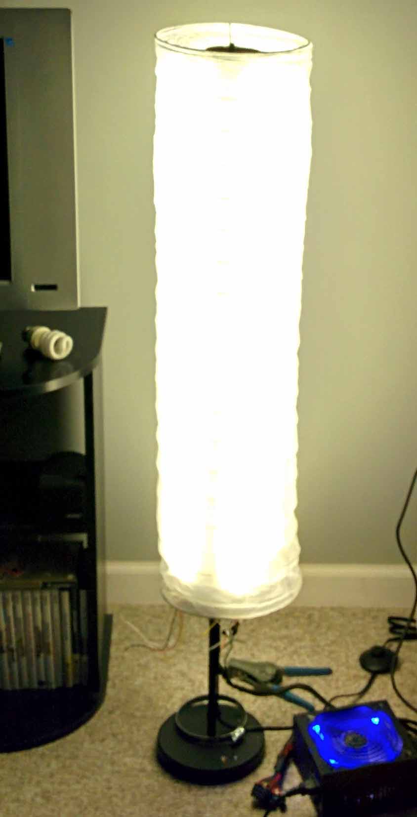
Right: Shows a test of the lamp illuminated by the RGB and warm white LED strips.
As you can see, the LEDs provided a much more uniform light which was a big improvement over the original light bulb configuration. The LEDs were also much brighter. Next, adding an Arduino and MOSFETs allowed me to dim the LEDs and control the color and intensity of the light. Since the Arduino can't handle the amount of power that is required to run the LED strips, I soldered together a simple board that had 5 IRLB8721 MOSFETs. The MOSFETs served as switches that the Arduino could control. Using the Arduino, I was successful at using PWM dimming on the LED strips. I could make the lights any color or turn them all on for a nice natural white. I added an IR receiver (TSOP38238) to the Arduino so that I could integrate an IR remote to easily control the lights. Finally, I installed a single strip of individually addressable LEDs (WS2812) onto the front of the cardboard tubes so that I could display a light show.
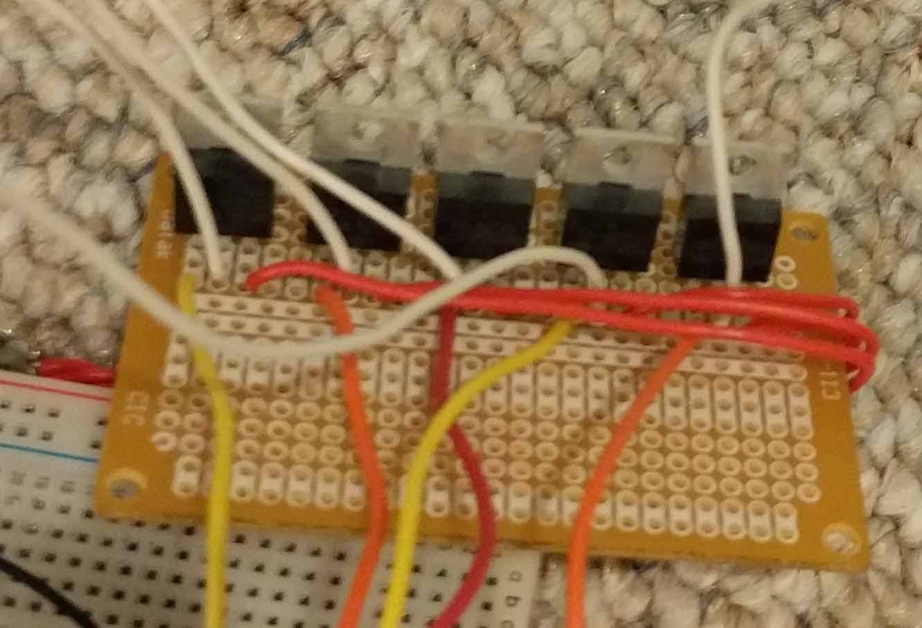
The control board has 5 MOSFETS - one for each LED channel (warm white, red, green, blue).
The fifth MOSFET is to enable/disable the WS2812 LED strip.
The LED Towers can be many different color temperatures of white: from warm(amber) to cold(blue/violet).
This is achieved by adding a small amount of red, green, or blue to the warm white.
8x8 LED Matrix
I always wanted to make a LED Matrix that could display pictures and text. This was my first attempt at trying to achieve that. After taking EECS 270 at U of M, I had a sufficient understanding of shift registers and transistors to tackle this project.
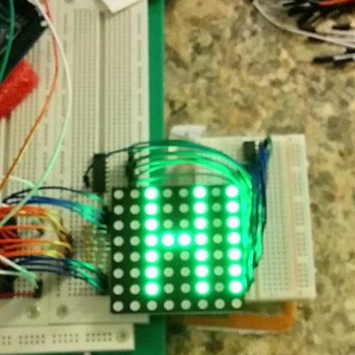
This was my first time using an Arduino in a project. The Arduino's ability to handle a SPI interface made it a good choice for this endeavor. It was very easy to send information into the shift registers and trigger the latch to illuminate the green LEDs. Based on the way this particular LED Matrix worked, the goal was to illuminate column by column. There was a common cathode for each column and an anode for each row. Using Arduino, I quickly flickered each column's LEDs so that it appeared that the entire matrix was on. It was even possible to flicker a pixel less often and get a result similar to that of PWM dimming (this is not captured well by the camera).
My methodology for this project was creating an 8x8 2D array in memory on the Arduino which the matrix displayed every time the display function was called. I also hand made the characters A-Z so that basic strings could be displayed.
8x8 Matrix displaying "Hello World".
This Matrix is actually RGB capable, and I did experiment with displaying colored images and colored text. Unfortunately, the wiring got very ugly very quickly.
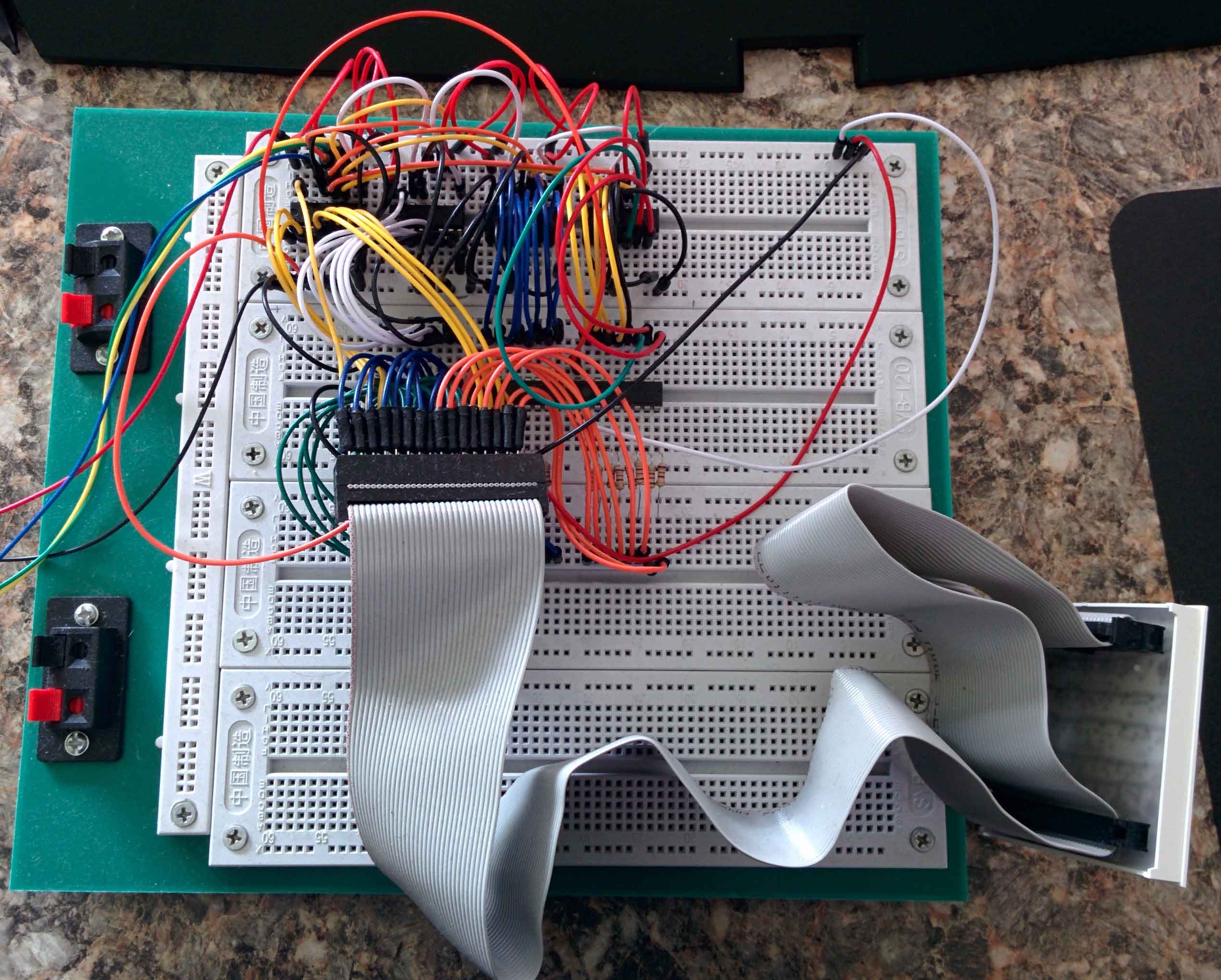
Organized Chaos.
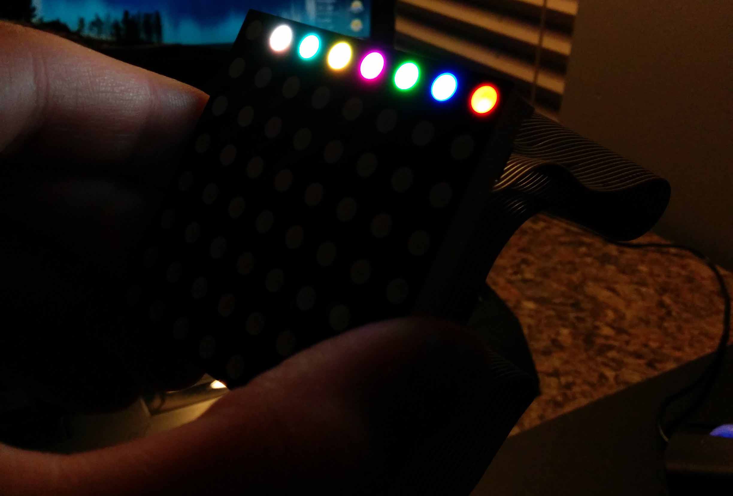
8x8 Matrix color test showing white, cyan, yellow, violet, green, blue, and red.
This is a good example of why it is important to minimize the amount of wires by using serialized data.